High-frequency power amplifiers are built according to a circuit containing amplification stages, a filter and automation circuits. Amplifiers are characterized by nominal output and minimum input power, operating frequency range, efficiency, sensitivity to load changes, level of unwanted vibrations, stability and reliability of operation, weight, dimensions, cost.
The currently obtained maximum values of the output power at frequencies up to 100 MHz are several tens of kilowatts. With a significantly lower power delivered by individual transistors (no more than 200 W), these values are achieved by special signal combining devices, among which power dividers and adders are the most common. There are many varieties of these devices. According to the magnitude of the phase shift, they are divided into in-phase (with a phase shift of the summed signals φ = 0), antiphase (φ = i), quadrature (φ = n / 2), etc.; by type of execution - with distributed and lumped elements; by the method of connection with the load - for serial and parallel, etc.
One of the main requirements for signal combining devices is to ensure the least mutual influence of individual modules, the powers of which are summed up (the so-called module decoupling). Let's see how this requirement is met in a simple common-mode transformer combiner. The circuit of such an adder on transformers T4- T6 together with a divider (on transformers T1- TK) and summed stages (on transistors VT1 and VT2) without bias and power circuits is shown in Fig. 5.4. Transformers T4- T6 have transformation ratios, respectively, 1.1 and 1 / V2 (here r n is the load resistance, R B is a ballast resistor, the resistance of which is 2 g n). Under normal operating conditions, when the voltages across the collectors are in phase and their amplitudes are equal, there is no current in the ballast resistor. Transformer T6 leads to two series-connected transformer windings T4 and T5 resistance 2r n, so that on the collector of each transistor the load resistance is r n. Imagine now that the collector of the transistor VT2 turned out to be closed with its emitter. In this case, the secondary winding of the transformer T5 represents an extremely low resistance for the HF signal, so that the resistance 2r n, reduced to the primary winding of the transformer T6, completely reduced to the secondary winding of the transformer T4, a therefore, to the collector of the transistor VT1. But in parallel VT1 in this case, a ballast resistor of the same resistance is connected, that is, despite the change in the operating mode, in the second stage the operating conditions of the first stage have not changed - it still operates on the load resistance r n. But, since half of its power now goes to the ballast resistor, only half the power of one stage remains in the load, which is 4 times less than the power given by the amplifier to the load before normal operating conditions change. The more stages are used to obtain the output power, the less the change in operating conditions in one stage or another affects the total power in the load. For example, in an amplifier with an output power of 4.5 kW, resulting from the summation of the powers of 32 transistor stages, when one stage fails, the output power decreases to only 4.3 kW. Thus, a very small mutual influence of the cascades in the power addition device makes it possible, using the amplifying properties of each transistor to the maximum, to ensure high reliability of its operation, and, consequently, the trouble-free operation of the power amplifier as a whole.
Rice. 5.4. Amplifier circuit with power addition on transformers
The summing device is selected based on the nature and operating conditions of the amplifier, since when solving the main task - the addition of signals - it is possible, using certain features of a particular type of adder, to improve other characteristics of the amplifier, for example, to weaken some types of unwanted oscillations or to reduce the sensitivity to load mismatch ...
Satisfactory decoupling of the modules, as well as a low level of unwanted third-order oscillations, low sensitivity to load changes and a weak effect of the summed stages on the preamplifier are obtained when using power quadrature adders. Antiphase combiners suppress unwanted second-order oscillations with satisfactory decoupling. The alternation of quadrature and antiphase adding devices, for example, when two modules are added antiphase, and pairs of modules combined in this way are quadrature, to a large extent combines the advantages of both types of adders. For these reasons, quadrature and antiphase adders and power dividers, made, for example, on long coaxial or strip lines, transformers, are widely used in amplifiers with an output power of 10 W and above.
The next parameter of the amplifier - the minimum input power - is determined by the permissible noise level and stability of operation and, in this regard, depends on the circuit, operating mode and design of the amplifier. The effect of noise on amplifier sensitivity is explained as follows. It is known that the noise power brought to the amplifier input is determined by the formula P w = 4kTF w Df, where k - Boltzmann's constant; T- absolute temperature; F m is the noise figure;
Af is the bandwidth in which the
R sh. But for a given signal-to-noise ratio TO NS at the amplifier output power of the input signal R with should not be less than R NS TO NS . It follows that the minimum allowable value of the input signal, thus characterizing the sensitivity of the amplifier, is defined as P C tsh = 4kTF u K w Df. Given the TO NS and Af all quantities included in this expression are known, with the exception of F JI. With the help of well-known relations, it is easy to show that in a nonlinear amplifier, which in the general case is a power amplifier, with a sufficiently large power gain of the first stage
where F sh1 is the noise figure of the first stage; at t + 1 is the ratio of the noise power amplification factors to the signal power amplification factor in the (m + 1) th stage of the amplifier containing NS cascades. Depending on the mode of operation of the cascade, this ratio is determined by the formula
coefficients included in this formula are found in tables. For example, for a four-stage 50 W amplifier at F m 1 = 6, Y 2 = 1.6, Yz = 1.7, Y 4 = 1.9 we have F NS =31, that with K w = 120 dB, Df = 20 kHz and 4kT = 1.62 * 10-20 W / Hz gives P W = 1 * 10 -14 W and P cmin = 10 MW, i.e., under the stipulated conditions, the minimum the permissible value of the input signal is characterized by a voltage of about 1 V at a resistance of 75 ohms. Note that the above definition of sensitivity is valid if a signal acts at the amplifier input, in which the noise power is at least an order of magnitude lower than the amplifier's own noise power reduced to the input, since otherwise an acceptable signal-to-noise ratio will not be obtained Ksh. If this difference in the values of the input noise is not observed, then to ensure the required value of K w between the signal sources and the amplifier, a selective circuit must be installed, leading to the necessary noise suppression at a given detuning from the operating frequency.

Rice. 5.7. Scheme amplifier with an output power of 15 W for the frequency range 2 - 30 MHz
Table 5.1
|
Parameter |
Meaning |
|
|
Output power, W, not less | ||
|
Supply voltage, V | ||
|
Load resistance, Ohm | ||
|
Input impedance (with VSWR<1,6), Ом | ||
|
Input voltage, V, not less | ||
|
Second harmonic level, dB, no more | ||
|
Third harmonic level, dB, no more | ||
|
The level of combination oscillations of the third order at the peak of the envelope of a two-tone test signal, dB, no more | ||
|
The level of intermodulation oscillations of the third order in relation to the value that caused these oscillations, interference in the load circuit, dB, no more | ||
|
Consumption current at rated output power in the mode of one-tone test signal, A, not more | ||
|
Ambient operating temperature range (at transistor housing temperature no more than + 110 ° С), deg | ||

Rice. 5.8. Amplifier circuit with 80 W output power for the frequency range 2 - 30 MHz
Table 5.2
|
Designation |
The number of turns in the primary f and secondary II windings, wire brand, type of winding, features of the structure |
|
|
T1(see figure 5.7) |
2 columns of 6 toroidal cores each, 1000NM-ZB, K5HZH XL, 5 |
I - 3 turns with MPO-0.2 wire; II - 1 turn of a tubular structure with a branch from the middle; I winding is located inside II |
|
T2(see figure 5.7) |
2 columns of 6 toroidal cores each, 1000NM-ZB, K5HZH X1, 5 |
I - 6 turns with MPO-0.2 wire; II - 1 turn of a tubular structure with a branch from the middle; I winding is located inside II |
|
(see fig. 5.7) |
1 toroidal core, 400NN-4, K 12X6X4, 5 |
I, II - 6 turns of 12 twisted wires PEV-0.14, divided into 2 groups of 6 wires; III - 1 turn of MGShV-0.35 wire 10 cm long |
|
(see fig. 5.7) |
1 toroidal core, 400NN-4, K20X 12X6 |
I - 2 sections of 3.5 turns with MGTFE-0.14 wire; II-5.5 turns with MGTFE-0.14 wire |
|
L3, L4 (see fig.5.7, fig.5.8) |
1 toroidal core, YOOONM-ZB, K 10X6X3 |
I - 5 turns of wire PEV-0.43 |
|
L5 (see figure 5.8) |
2 toroidal cores, 400NN-4, K 12X6X4, 5 |
I - 8 turns of wire PEV-0.43 |
|
T1(see figure 5.8) |
2 columns of 6 toroidal cores each, YOOONM-ZB, K5H |
1 - 2 coil wire MPO-0.2; II - 1 turn of a tubular structure with a branch from the middle; I - the winding is located inside II |
|
T2(see figure 5.8) |
2 columns of 5 toroidal cores each, YOOONM-ZB, K7X X4X2 |
I - 2 turns of 2 wires MPO-0.2 each with a tap from the connection point of the end of 1 wire with beginning 2; II - 1 a coil of a tubular structure with an outlet from the middle; I winding is located inside II |
The end of the table. 5.2
|
Designation |
Transformer or choke core design, type of material and size |
Number of turns in primary I and secondary II windings, wire brand, type of winding, design features |
|
TK(see figure 5.8) |
1 toroidal core, 100NN-4, K 16X8X6 |
I - 6 turns of 16 stranded wires PEV-0.31, divided into 2 groups of 8 wires, with a tap from the junction point of the end of group 1 with the beginning of 2; II - 1 turn of wire MGShV-0.35 10 cm |
|
T4(see figure 5.8) |
2 columns of 7 toroidal cores each, 400HN-4, K 16X8X6 |
I - 1 turn of a tubular structure with a branch from the middle; II - 2 turns of 10 wires MPO-0.2, connected in parallel; II winding is located inside I |
The bandwidth at high power levels is largely determined by interstage matching circuits, which are specially designed broadband transformers, as well as amplitude-frequency characteristic correction circuits and feedback circuits. So, in fig. Figures 5.7 and 5.8 show amplifier circuits with an output power of 15 and 80 W for radio transmitters with a power of 10 and 50 W operating in the range of 2-30 MHz. Their main characteristics are given in table. 5.1, and the data of the used transformers and chokes are in table. 5.2. The features of these amplifiers are a relatively low level of unwanted oscillations and a relatively small unevenness of the amplitude-frequency response. These parameters, for example, in an 80 W amplifier, are achieved by using frequency-dependent negative feedback in the output stage (from the secondary winding of the transformer TK through resistors R11 and R12 to the base of transistors VT3 and VT4) and in the pre-final stage (using resistors R4 - R7), and also corrective circuits C2 R2, C3 R3 and R1 L1 C1.
It is also possible to reduce the gain flatness in the frequency band by using correction circuits at the input of the final stage (capacitor C7 and inductance of conductors AB and VG, which are strips of foil 30 mm long and 4 mm wide) and at the amplifier output (transformer inductance T4 and capacitor C 13). The broadband transformers used in these amplifiers are able to provide satisfactory matching not only in the 2-30 MHz range, but also at higher frequencies. However, at frequencies above 30 MHz, better performance is obtained with strip line transformers without ferrite materials. Such transformers, for example, were used in an amplifier with an output power of 80 W in the range of 30 - 80 MHz (Table 5.3), the diagram of which is shown in Fig. 5.9. A feature of this amplifier is the use of bipolar and field-effect transistors at the same time. This combination made it possible to improve the noise characteristics in relation to the use of only bipolar transistors, and in comparison with the use of only field devices, to improve the energy characteristics of the amplifier.
Table 5.3
|
Designation |
Transformer design |
|
T7, T 6 |
Directional coupler in the form of a microstrip line 720 mm long and 1.5 mm wide, made on a double-sided foil fiberglass laminate with a size of 75X20X0.5 mm and placed between two glass fiber laminate plates, each of which is foil on the outside. Overall dimensions 75X20X3.5 mm |
|
T2, TK |
6 turns of twisting of two wires PEV-0.41 with a twisting pitch of 3 turns per 1 cm on a toroidal core MRUOF-2-8 K7X4HZ |
|
T4, T5 |
6 turns of twisting of two wires PEV2-0.41 with a twist pitch of 3 turns per 1 cm on a toroidal core MRUOF-2-8 K12X7X6 |
|
I winding of 1 turn of a printed conductor with a width of 5 mm and II a winding of 2 turns of a printed conductor with a width of 2 mm, placed opposite each other on different sides of a plate of double-sided foil fiberglass with a size of 80X18X0.5 mm, enclosed between insulating fiberglass plates |
|
|
A printed conductor with a total length of 370 mm and a width of 10 mm at a distance of 168 mm and a width, smoothly varying from 10 to 3 mm, at a distance of 168 - 370 mm, made on fiberglass FTS - 1 - 35 - B - 0.12. The first winding is the first section of the 168 mm long conductor; the second winding starts from the middle of the first and ends at the end of the conductor. The entire conductor is wound in a spiral on a dielectric frame |
![]()
Rice. 5.9 Circuit of an amplifier with an output power of 80 W for a frequency range of 30 --- 80 MHz
An important parameter of an RF amplifier is its efficiency. This parameter depends on the purpose of the amplifier, its operating conditions and, as a consequence, on the construction scheme and the semiconductor devices used. It is 40 - 90% for signal amplifiers with constant or switched amplitude (for example, with frequency and phase modulation, frequency and amplitude telegraphy) and 30 - 60% for linear amplifiers with amplitude modulation. The lower of the indicated values are explained by the use of energetically unfavorable, but providing linear amplification, undervoltage modes in all stages, as well as mode A in the preliminary, and often in the pre-final stage of the amplifier. Higher values are typical for the key mode of amplification of signals with constant or switched amplitude (80 - 90%) or for amplitude-modulated signals (50 - 60%) when using the method of separate amplification of signal components. For example, an efficiency of at least 80% was obtained in a 4.5 kW broadband amplifier with an output stage on 32 transistors, built taking into account the general recommendations for the key mode and when taking measures to eliminate through currents. However, despite the obvious energy advantages of the key mode of operation, it is still relatively rarely used in RF amplifiers. This is due to a number of features, which, for example, include criticality to load changes, a high level of unwanted oscillations, a high probability of exceeding the maximum permissible transistor voltages and the difficulty of adjusting when obtaining the necessary phase-frequency characteristics, the stability of which must be ensured under conditions of changing load, supply voltage and temperature. environment. In addition, for the implementation of the key mode at high frequencies, transistors with extremely short duration of transients when turning on and off are required.
A promising direction for increasing the energy characteristics of amplifiers of an amplitude-modulated signal is signal quantization by level with separate amplification of discrete components and their subsequent summation taking into account phase shifts.
In increasing the efficiency of amplifiers, the quality of matching with the load, taking into account the possibility of its change, plays an important role. Currently, this issue is simple and at the same time most effectively solved by using ferrite valves and circulators. However, this is the case at relatively high frequencies, at least above 80 MHz. With decreasing frequency, the efficiency of using ferrite decouplers drops sharply. In this regard, it is of interest to study and subsequent industrial development of semiconductor nonreciprocal devices with the properties of circulators, which in principle allow operation at low frequencies. If the use of valves or circulators is not possible, satisfactory results are obtained by combining conventional matching devices with automatic control of the amplifier operating mode. So, increasing the supply voltage with an increase in the load resistance (with a constant or slightly reduced excitation) and decreasing it with a decrease in the load resistance with an increase in excitation, it is possible to obtain not only a constant output power, but also to maintain the high efficiency value, which was received in nominal mode. The possibilities of this method of stabilizing the output power, however, are limited by the maximum permissible currents and voltages of the used transistor, as well as by the technical capabilities of matching low resistances. For these reasons, the currently implemented region of load resistances, in which it is still possible to achieve a relatively stable output power in this way, is limited, as shown by tests of an amplifier with an output power of 4.5 kW, by a VSWR value not exceeding 3.
The effect of low sensitivity to load mismatch can also be obtained when building an amplifier according to a power addition circuit using quadrature adders and power dividers. With an appropriate excitation voltage, such an amplifier can be achieved, despite the change in the operating mode of each of the summed stages, a slight change in the total consumption current and the total output power. When testing such amplifiers, it was noted that the change in output power with a load mismatch turns out to be the same as in linear circuits, that is, it is described by an expression close to P / P n = 4p / (1 + p) 2, where P n and R- power at rated and unmatched load, ar - VSWR, characterizing the degree of mismatch. Such a change, on average, as shown by comparative tests, is about half that of an amplifier built, for example, according to a push-pull circuit.
There are other ways to reduce the sensitivity of the amplifier to load mismatch, but all of them, to one degree or another, are inferior to those considered.
Recently, the level of unwanted oscillations arising in the process of amplifying the useful signal has become one of the main parameters of the amplifier. Such oscillations appear in the power amplifier due to nonlinear processes under the influence of the useful signal f and interference coming from the signal shaping path (f f), the power source (f p) and the antenna of the radio transmitter (f a). Extraneous vibrations (interference) from the signal formation path lead to unwanted emissions of the radio transmitting device not only at the frequencies of these vibrations ff, but also at the frequencies formed under their influence of combination vibrations mf± nf f . The level of such emissions is determined by the relative level of unwanted oscillations at the output of the formation path, its change (conversion) in the power amplifier, as well as the filtering and radiating properties of the radio transmitting device nodes following the amplifier. The change in the noise / signal ratio in the amplifier (K y) is determined by the transistor switching circuit, the operation mode of the stages, the value and frequency of the useful signal and noise.
The largest change in the noise / signal ratio is observed in an amplifier with an OE, as well as at a low output impedance of the signal source r G in an amplifier with OB and at a low load resistance r n in an amplifier with OK. With an increase in r g in an amplifier with OB and r n in an amplifier with O "K K y -> 1. When the amplifier operates in modes A and B with any switching on of the transistor, the relative level of interference does not change; a shift in the mode of operation towards mode C leads to an increase, and towards mode AB, on the contrary, to a decrease in the relative level of interference; at the same time, the increase is more noticeable than a decrease. An increase in the mode strength decreases the relative level of interference. The larger the value of the useful signal, the more the interference / signal ratio changes with the same operating mode. With an increase in the frequency of the signal and interference, the change the interference / signal ratio decreases.
The combination oscillations arising under the influence of interference are especially dangerous when the amplifier operates in C mode, where their level at the amplifier output is commensurate with the noise level. With a change in the operating mode from C to A, the level of combination oscillations of the second order (f ± ff) decreases monotonically, and the third (2f ± ff) passes through 0 in mode B and upon reaching a minimum in the region of negative values, indicating a change in the phase of the oscillations to the opposite , when approaching mode A tends to 0.
All other things being equal, the amplifier with OK, and then amplifiers with OB and OE, are distinguished by the greatest suppression of combination oscillations. In a multi-stage amplifier, in contrast to a single-stage amplifier, the interference for each next stage, starting from the second, is not only amplified unwanted oscillations of the formation path, but also combination and harmonic oscillations of the previous stages. The influence of the second harmonic is especially great; it increases the levels of second- and third-order combinational oscillations and decreases the interference / signal ratios. This is mainly manifested in mode C and is actually absent in A. Under its action, the linear mode of operation (K y = 1) shifts from mode B to C. These changes are directly opposite if the phase of the second harmonic is somehow artificially changed to l.
A low level of combination oscillations, a slight deterioration of the noise / signal ratio and at the same time acceptable energy characteristics are characteristic of an amplifier, the preliminary stages of which operate in modes A - B, and the output stages in modes B - C. When the transistors are turned on according to the OK scheme, modes B - C can be used and in the preliminary stages, but in the output stage, switching on according to the OK scheme is unacceptable due to the high susceptibility of the amplifier to the signals of extraneous radio transmitters. The best for the output stage is the inclusion of the device according to the OB or OE scheme. In this case, the deterioration of the noise / signal ratio in the amplifier at a low level of combination oscillations can be at most 3 dB. But with an illiterate design of the amplifier, this value can increase to 20 dB, and the highest level of unwanted oscillations will be not only at the frequency of the interference, but also at the frequencies caused by this interference of the combination oscillations.
When there is a frequency detuning between the useful signal and the interference, the interference is most effectively suppressed in amplifiers with filters. Suppression is realized both with electronically commutated filters and by building an amplifier based on a powerful self-oscillator controlled by a phase-locked loop system. In the latter case, it is possible to obtain attenuation of unwanted components - up to 70 - 80 dB, starting from a 5% offset of their frequency from the frequency of the useful signal.
Currently existing transistors in the undervoltage mode of the cascade operation allow obtaining the level of intermodulation oscillations of the third order - (15 - 30) dB in relation to the interference that caused them when switched on according to the OE circuit, about 15 dB less when switched on according to the OB circuit and, conversely, 15 dB more when switched on according to the OK scheme. Additional suppression of about 15 - 20 dB can be obtained using the quadrature summation of the signals of the modules in the output stage and, at least, 15 dB, using a ferrite valve or circulator at the amplifier output.
The highest level of unwanted oscillations is observed at the harmonics of the useful signal. In a single-stage amplifier without taking any measures to suppress them, this level for the second and third harmonics is usually - (15 - 20) dB. By switching on cascades according to the power addition scheme using quadrature and antiphase adders and dividers, it can be reduced to - (30 - 40) dB. If a filter bank is installed behind the amplifier, then this level is reduced by the amount of attenuation of the corresponding filter in the stop band.
Filters can be used to achieve a high level of harmonic suppression. However, it should be emphasized that the harmonics are attenuated; to a level below - 120 dB is possible only with very careful shielding of the RF stages and the elimination of various contact connections in the path after the power amplifier, including RF connectors, in which harmonic oscillations with the same level can be formed.
As you can see, the existing technical solutions provide high suppression of unwanted vibrations. However, in a number of cases, it still turns out to be insufficient for the normal operation of the equipment. So, when the transceivers located on mobile devices approach each other or when working as part of radio complexes, where a wide variety of equipment is concentrated and must function in extremely limited space, radio receivers often cannot work with their correspondents, as soon as a nearby radio transmitter of another communication line is turned on. This is due to the exposure of the receivers to some unwanted emissions from the radio transmitter. These primarily include noise. Despite the low level, it is they who fly
the greatest danger in these conditions, since, having a continuous spectrum and a weakly varying spectral density with detuning, can, if the necessary measures are not taken, almost completely paralyze the operation of the nearby receivers.
A great danger in the situation under consideration is represented by interference from the transmitter signal formation path and the combination oscillations formed by them in the power amplifier, which, like noise, occupy a wide frequency range and cannot be significantly minimized when constructing an amplifier according to the previously considered principle of direct cascade power amplification.
Broadband high frequency amplifiers
In most cases of amateur radio design, monolithic integrated circuits should be preferred when designing high-frequency devices. However, when high sensitivity and wide dynamic range are required, the following reactive feedback amplifier circuits may be useful.
The amplifier in Fig. 2.1-1 is intended for use in the input stages of UHF and UHF. It has a wide dynamic range and a linear frequency response over a wide frequency range. With some change in inductance and capacitance, the amplifier is applicable in the range from 1 to 300 MHz.
The diagram in Fig. 2.1-2 is identical to the diagram in Fig. 2.1-1 except that in this case the amplifier can be directly connected to a balanced load. If an output impedance different from the one indicated in the diagram is required, then the number of turns in the windings (1-2) and (1 "-2") of the high-frequency transformer Tr1 is changed (the dependence here is quadratic, for example, when the number of turns in these windings is 5 (1-2 ) +5 (1 "-2") we get an output impedance of 50 Ohm. And at 20 (1-2) +20 (1 "-2") - 800 Ohm).
The amplifier in Fig. 2.1-3 is intended for use in stages that require high input impedance. It also provides wide dynamic range and linear response. The input impedance of the amplifier is more than 1 kOhm. If it is necessary to reduce this value, the choke L1 is replaced with a resistor of the appropriate rating or its inductance is changed so that the reactance at the operating frequency is equal to the required input resistance.
All described amplifiers use broadband transformers of the same design. Pay attention to that. that the ferrite core used must be designed for use in the operating frequency range of the amplifier.


The number of turns in transformers is determined by both the type (size and permeability) of the core and the frequency range in which the amplifier is supposed to be used.

The indicated ratios are also valid for the transformers used in the mixer circuits below. The location and density of the winding are selected to achieve the best chain parameters.
In fig. 2.1-4, for example, a diagram of a universal generator is shown using an amplifier according to the scheme 2.1-3 Such a generator can be used in radio stations, as a local oscillator in receiving devices or for measuring purposes.

Rice. 2.1-1 Amplifier stage for the input paths of high-sensitivity UHF and UHF
Image:
Rice. 2.1-2 Amplifier stage with balanced output
Image:
Rice. 2.1-3 High Input Impedance Amplifier Stage
Image:
Rice. 2.1-4 Universal RF generator
Image:
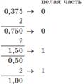
F.1 Determination of the number of turns in transformers
Image:
2. Mixers
Mixers
Mixers in fig. 2.1-5 and fig. 2.1-6 operate at frequencies of 1-300 MHz (see above for inductance calculation formulas). Both schemes introduce an attenuation of 5 ... 6.5 dB, provide a wide bandwidth and are applicable in a wide variety of designs.

Rice. 2.1-5 Simple Balanced and Ring Balanced Mixer
Image:
2. Circuits for amplification and processing of low and medium frequency signals.
Circuits for amplification and processing of low and medium frequency signals.
1. Low noise preamplifier with low input impedance.
Low noise preamplifier with low input impedance

The amplifier in Fig. 2.2-1 has an input impedance of 5 Ohm, obtained through the use of POS and OOS in certain ratios. Part of the emitter signal of the transistor VT2 arriving at the base VT1 creates OOS, and the collector signal VT3 - POS. Due to the low input impedance, the noise characteristics of the amplifier are significantly improved. The spectral density of the intrinsic noise with an open input is 2 * 10 (-4) μV / Hz. The gain is 40. The bandwidth is determined by the capacitance C1.
Rice. 2.2-1 Low Noise Preamplifier with Low Input Impedance
Image:
2. Low noise preamplifier with high input impedance.
Low noise preamplifier with high input impedance
At the amplifier input in Fig. 2.2-2 a field-effect transistor is used in a circuit with an OI. The second stage is made on a bipolar transistor according to the OE circuit. The amplifier has two feedback loops. From the collector of the transistor VT2 through the chain R6, SZ, the feedback signal is fed to the source of the field-effect transistor, and from the source through the capacitor C2 and resistor R3 to the gate VT1. The presence of the second OOS allows increasing the input impedance of the amplifier to tens of megohms and reducing the input capacitance.
The gain can be set from 1 to 100, which also changes the bandwidth. For a gain of 4, the bandwidth is 100Hz-40MHz. Input impedance 30 MΩ, maximum output voltage 1.5 V.

Rice. 2.2-2 Low Noise Preamplifier with High Input Impedance
Image:
3. Microphone amplifier.
Microphone amplifier
In fig. 2.2-3 shows a diagram of a microphone amplifier built into the microphone holder and powered through a two-wire cable. The circuit works with dynamic microphones and is characterized by good noise immunity. The output signal is taken from the resistor R4. The bias to the base of the transistor VT1 and the temperature stabilization of the amplifier are provided by the divider R2 and R3. Resistor R1 is the load of the first stage and carries out feedback in the second stage. Feedback reduces harmonic distortion and provides an output impedance of 600 ohms. The bandwidth is 16-12500 Hz. Gain 200.

Rice. 2.2-3 Schematic diagram of a microphone amplifier
Image:
4. Microphone amplifier with correction, combined with a noise suppression circuit for radio stations and intercom.
Microphone amplifier with correction, combined with a noise suppression circuit for radio stations and intercoms
The diagram in Fig. 2.2-4 is built on the basis of the KR1401UD2 microcircuit, which contains four identical op amps. The first part of the circuit (elements DA1.1. DA 1.2) performs
function of a microphone amplifier with subsequent correction of the frequency response, dynamic change of the gain depending on the signal level and limiting the amplitude of the output signal (which is necessary, for example, to limit the modulation depth in radio stations). The second part of the circuit (DA1.3, DA1.4)

suppresses noise in the low-frequency signal, which is necessary to prevent the reproduction of a constant background sound in radio stations, intercoms, etc.
The level of operation of the noise suppression system is regulated by the resistor R13, the volume of the low frequency output signal - by the resistor R 17. The trimmers R3, R5 are set to the position of the best audibility of the useful signal with the greatest attenuation of noise when the ShP is off. Capacitor C16 is selected to provide the required bandwidth for the microphone amplifier. The value of the resistor R24 depends on the design of the sound receiver and the type of microphone used. You can also say about the resistor R22, which regulates the gain of the stage on the op-amp DA1.2.
Rice. 2.2-4 Microphone amplifier circuit with frequency response correction and wide dynamic range, combined with noise suppression circuit
Image:
5. Device for suppressing impulse noise.
Impulse noise suppressor
In fig. 2.2-5 shows a schematic diagram of a symmetrical limiter, which limits short-term impulse noise. Bandwidth up to 100 kHz. With a useful signal frequency of 3 kHz, the level of impulse noise exceeding the signal level by 300-500 times and the duration of the noise 20-30 μs, the circuit reduces the noise level by 30-40 dB.

Rice. 2.2-5 Diagram of a device for suppressing impulse noise
Image:
6. Serial signal mixer.
Serial signal mixer
The mixer in fig. 2.2-6 is built on two field-effect transistors. The first transistor is the dynamic load of the second. The heterodyne signal supplied to the VT2 gate is modulated by the converted signal supplied to the VT1 gate. For small values of the input signal, the output signal is linearly dependent on the input signal. When the input signal is more than 1.2V, nonlinear distortion appears. The mixer operates in the audio frequency range. At frequencies above 500 kHz, the interelectrode capacitances of the FET begin to affect, which reduce the transfer coefficient of the mixer.

Rice. 2.2-6 Schematic diagram of a serial signal mixer
Image:
3. Elements of automation devices.
Elements of automation devices.
1. Amplifier for capacitive sensors.

Lambda diode


Image:
Image:
Rice. 2.3-3 Lambda diode
Image:
2. Cable amplifier for remote sensor.
Amplifier for capacitive sensors
In fig. 2.3-1 is a diagram of a preamplifier for capacitive sensors with low voltage power supply. The consumed current is 10 mA, the input resistance is 1 MΩ, the output resistance is 5 kΩ. Cutoff voltage VT1 must be less than 1 V.
Remote sensor cable amplifier
To transmit signals from sensors remote from measuring instruments, amplifiers are used, the output signal and supply voltage in which are supplied through one cable. In fig. 2.3-2 shows a diagram with 100% OOS (Rin = 2 * 10 ^ 3 MOhm, Svh = 2.5 pF). The transmission coefficient in the frequency range from 10 Hz to 50 MHz is in the range of 0.9-0.92. The noise of the amplifier in the frequency range 5 Hz-300 kHz is 10 μV with the input closed. To reduce external noise on the input circuits, careful shielding of the entire amplifier is required, especially the input circuits and the sensor.
Lambda diode
The device in Fig. 2.3-3 consists of two field-effect transistors of different conductivity. At zero gate voltage, both transistors conduct. In the scheme, they are included in the OOS circuit after
consistently in relation to one another. The current flowing through the transistor VT1 creates a voltage drop across VT2, which closes VT1. In turn, the resistance of VT2 changes depending on the voltage drop across VT1. Thus, as the flowing current increases, both transistors tend to close. When the voltage drop across the transistors reaches the cut-off level, the current flowing will be close to zero. For the KP103I transistor, the cut-off voltage is 4 V, for the KP3O3D transistor, the cut-off voltage is 8 V.
Rice. 2.3-1 Amplifier for capacitive sensors
Rice. 2.3-2 Cable amplifier for remote sensor
Rice. 2.3-3 Lambda diode
3. Lambda diode.
Amplifier for capacitive sensors
In fig. 2.3-1 is a diagram of a preamplifier for capacitive sensors with low voltage power supply. The consumed current is 10 mA, the input resistance is 1 MΩ, the output resistance is 5 kΩ. Cutoff voltage VT1 must be less than 1 V.
Remote sensor cable amplifier
To transmit signals from sensors remote from measuring instruments, amplifiers are used, the output signal and supply voltage in which are supplied through one cable. In fig. 2.3-2 shows a diagram with 100% OOS (Rin = 2 * 10 ^ 3 MOhm, Svh = 2.5 pF). The transmission coefficient in the frequency range from 10 Hz to 50 MHz is in the range of 0.9-0.92. The noise of the amplifier in the frequency range 5 Hz-300 kHz is 10 μV with the input closed. To reduce external noise on the input circuits, careful shielding of the entire amplifier is required, especially the input circuits and the sensor.
Lambda diode
The device in Fig. 2.3-3 consists of two field-effect transistors of different conductivity. At zero gate voltage, both transistors conduct. In the scheme, they are included in the OOS circuit after
consistently in relation to one another. The current flowing through the transistor VT1 creates a voltage drop across VT2, which closes VT1. In turn, the resistance of VT2 changes depending on the voltage drop across VT1. Thus, as the flowing current increases, both transistors tend to close. When the voltage drop across the transistors reaches the cut-off level, the current flowing will be close to zero. For the KP103I transistor, the cut-off voltage is 4 V, for the KP3O3D transistor, the cut-off voltage is 8 V.
Rice. 2.3-1 Amplifier for capacitive sensors
Rice. 2.3-2 Cable amplifier for remote sensor
Rice. 2.3-3 Lambda diode
4. Converters of voltage and current.
Voltage and current converters.
1. Voltage multipliers.
Voltage multipliers
When developing high-voltage circuits, the selected conversion circuit is of great importance to the simplicity and quality of the device. Below are several voltage multiplier circuits for use in a wide variety of devices.
In fig. 2.4-1 shows the voltage doubler circuits. Capacities in all doublers are chosen the same. The operating voltage of the capacitors should overlap with a margin that shown in the diagrams. Diodes must be selected accordingly. The more current is required in the load, the more capacitance the capacitors must have. Naturally, when the voltage rises with the help of diode-capacitive multipliers, the load current is proportionally reduced.

Similarly, multiplication is performed by three or more times.
The multiplier circuits shown here can be used in voltage-to-voltage converters. For example, a diagram of the use of a diode multiplier by 2 is shown (Fig. 2.4-5).
The converter (Fig. 2.4-5) consists of a generator assembled on transistors VT1, VT2 and a diode-capacitor multiplier. The generator frequency is determined by C 1 and resistors Rl, R2. The output signal of the generator goes through the multiplying chain and charges the capacitor C5. The multiplier is designed for an output current of up to 10 mA. To increase the load current, it is necessary to put an emitter follower after the generator and increase the capacitance of the capacitors C2-C4.


Rice. 2.4-1 Voltage Doubler Circuits
Image:
Rice. 2.4-2 Circuits for multiplying by three, six and eight
Image:
Rice. 2.4-3 Multiplier by four circuit, voltage converter
Image:
2. Converter "voltage-current".
Voltage-current converter
In the converter circuit in Fig. 2.4-6 collector current of transistor VT4 is determined by the expression: Ikvt4 = Uin / R1. This current causes a voltage drop across the collector-emitter junction of transistor VT1. Since VT1 and VT2 are of the same type, the voltage across VT2 will be the same, and, accordingly, the current flowing through VT2, VT3 will coincide with the current in VT4. The maximum output current is determined by the allowable power dissipation of the VT3 transistor. For currents above 5 mA, the conversion nonlinearity is no more than 1%. Any K544 series op amp can be used as DA1. K574, included according to the standard scheme.

Converter "current-voltage"
The converter in Fig. 2.4-7 is built on the principle of voltage amplification that occurs when current flows through the resistor R6. The circuit provides Uout = К * Iвх- Conversion factor of the circuit К = R6 * (R3 / R4). The resistor R2 is used to adjust the op-amp at Iin = 0. Part of the input current is branched off into the R1, R2, R3 circuit. Resistor R6 - wire-wound (nichrome).
This RF amplifier circuit of the transmitter (at 50 MHz) has 100 watts of output power. I used this UHF with my FT-736R for DX SSB. It amplifies the signal exactly 10 times. The device is perfect for taxi drivers' car radios operating in the 50 and 27 MHz bands (with re-tuning of the contours).
If you want to build this RF amplifier, build it on a double-sided PCB to increase the ground area. Transistor 2SC2782 needs a decent heatsink. The maximum output power is 120W.
RF power amplifier circuit

PCB drawing

Amplifier Specifications:
- Out Power: 10W
- Output Power: 100W
- Working Frequency: 50-52MHz
- Operating mode: FM - SSB
- Working Voltage: DC 10-16V
- Working Current: 10 amps.

The scheme was taken from one Chinese site and successfully repeated, only the elements of the detector for automatic transmission-reception switching were not used (crossed out in the diagram). To create UHF for frequencies from 100 megahertz - use.
It is generally accepted that the development of high-frequency amplifiers is much more complex than the development of low-frequency amplifiers. Indeed, in this case it is necessary to take into account a much larger number of various electromagnetic effects and processes in circuits. But it often turns out that the actual circuit design of such an amplifier rarely deviates from some template structure. The point here is that in the design of high-frequency amplifiers, they primarily strive not to increase the output power while minimizing linear and nonlinear distortions, but to achieve maximum sensitivity and high stability of the stage in a wide frequency range, i.e. The requirements for high frequency amplifiers are usually very different from those for low frequency amplifiers.
A typical structure of a high-frequency amplifier is a series connection of three links: an input matching link (these are usually quite simple \ (LC \) - chains that introduce minimal losses, ensuring matching with the previous stage and roughly shaping the frequency response), the main amplifying link (a transistor turned on with OE, OB or OK, possibly with an intra-stage OOS, providing stability and a wide dynamic range in a wide frequency range), an output filter that finally forms the frequency response of the stage and ensures matching at its output (here, rather complex \ (LC \) - filters, SAW filters, piezoceramic, quartz filters, etc.). Interstage couplings in high-frequency amplifiers are usually performed using capacitors, coupled inductances or high-frequency broadband transformers (here we deliberately omit the design issues of integrated amplifiers, this is a completely separate topic, and will be discussed later). Let us consider in order the reasons that so strictly regulate the described structure of the amplifier stage.
Various transistor switching circuits (OE, OB, OK) have different input and output parameters (which ones, we will analyze later). For high-frequency amplifiers, the issues of matching the input and output cascades are important (as the frequency increases, it becomes more important, and for microwave amplifiers it is generally mandatory). The lack of matching leads to an increase in signal distortion, its re-reflection back to the input of the previous stage, due to which the overall gain of the circuit decreases, and most importantly, to an increase in the instability of the circuit, which can lead to its self-excitation. To avoid all these effects, special precautions are taken when designing high-frequency circuits. impedance matching, i.e. the output impedance of the first stage should be equal (or, in extreme cases, should be lower) the input impedance of the subsequent stage (note that for low-frequency amplifiers, given the need to increase efficiency, we usually strive for the input impedance of the amplifier stage to be much higher cascade). It is to match the impedances at the input of the high-frequency stage that special circuits have to be switched on. Note also that it is not customary to include filters that are too complex and introduce rather high losses at the input of high-frequency amplifying stages (unless these are final stages). An already rather weak high-frequency signal can simply get lost in the noise after passing through such filters.
This begs a simple question: why is it necessary to so diligently control all possible feedback loops? The fact is that the presence or absence of such chains has a decisive effect on steadiness amplifier. There is a whole theory of stability that makes it possible to predict the behavior of a wide variety of circuits. The main problem here is that a circuit that seems to work normally during test tests, when a clean useful signal is applied to it, may turn out to be highly excitable outside the operating gain band, i.e. in a real device, where there is always some interference and unwanted intermodulation products operating outside the operating band, such a scheme will not work. Loss of stability causes significant nonlinear distortion of the signal, and in the limit the circuit can self-excite, turning from an amplifier into a generator. Do not think that this problem does not exist in low frequency amplifiers. But there it turns out to be much more predictable and controllable, so that it does not cause very serious difficulties in the design of amplifiers. But in high-frequency amplifiers, uncontrolled self-excitation can manifest itself even in carefully calculated and professionally assembled circuits.
Various problems in high-frequency amplification stages cause the overall gain of such stages to be much lower than the gain of similar low-frequency circuits. An additional problem is created by the numerous filters that shape the frequency response of the amplifier, but at the same time also significantly attenuate the useful signal. Thus, to provide a sufficiently high gain at a high frequency, it is necessary to build multi-stage amplifiers with a number of stages that significantly exceed what we are used to seeing in low-frequency circuits.
In the general case, there is no universal technique for constructing circuits of high-frequency amplifiers, and the above structure is only a certain average statistical option that can change significantly if necessary. It makes sense to single out two broad classes of amplifiers: broadband(these include and aperiodic) and narrowband(these include and resonant) amplifiers.
Narrowband amplifiers. The block diagram of a narrowband high-frequency amplifier includes all the standard links described above. But besides this, the narrowband amplifier may include additional passive circuits designed to form the required bandwidth and ensure the stability of the amplifier outside the operating frequency band ( stabilizing chains).
The problem of bandwidth formation is very important in the design of narrowband amplifiers, since high frequency transistors are active in a wide frequency band. You can form the required bandwidth, for example, using a lumped selection filter (FSS), included at the input or output of the transistor. FSS at the input attenuates the effect of interference, prevents nonlinear distortions caused by their interaction with the signal (intermodulation distortion), and thereby increases the noise immunity of the amplifier. However, the filter included at the input introduces additional losses to the amplifier and increases its noise figure. The narrower the filter loss at the center frequency of the passband, the greater the narrower the bandwidth. More stringent requirements are imposed on the FSS at the input than on the filter included at the output of the transistor. Another possible way to form the bandwidth is with the help of resonant links connected in series with the transistor or in the feedback circuit. Resonant amplifiers have a narrow bandwidth and high gain. Their main negative feature is their lower stability in comparison with broadband cascades. Outside the operating frequency band, in the area of potential instability, the amplifier can be excited by interference and intermodulation products. To prevent this, stabilizing circuits with losses are introduced into the circuits of narrow-band amplifiers, which do not affect the operation of the cascade in the operating frequency band, but shunt the signal flow circuits in areas of potential instability.
Note that functions such as impedance matching, bandwidth shaping, and amplifier stability do not have to be performed by different passive circuits — a single circuit can be used to perform several functions at once.
Broadband amplifiers. When designing broadband amplifiers, one should take into account the fact that the gain at any turning on of the transistor decreases with increasing frequency, therefore, the calculation of such amplifiers and the matching of loads are usually performed not at the center, but at the upper frequency of the operating range (such amplifiers are often used as matching circuits broadband transformers). Excessive amplification, which occurs at the lower frequencies of the range, is eliminated by the so-called leveling chains... The latter can be made in the form of reactive or dissipative circuits (the simplest example of an equalizing circuit is an ordinary capacitor connected in series to the signal flow circuit; at the upper frequency of the operating range, its resistance is lower than the resistance at the lower frequency, i.e. low-frequency signals when flowing through such circuit will be more suppressed than high frequency signals).
In amplifiers with reactive equalizing circuits, the gain correction in the passband is carried out due to the mismatch (increase in the reflection coefficient) at the input of the amplifier with decreasing frequency. However, with a strong mismatch, the amplifiers can self-excite. In this case, it is preferable to use dissipative circuits.
When dissipative equalizing circuits are used, the excess gain is compensated for in the absorbing elements of the circuits, the damping of which increases with decreasing frequency (recall the example with a capacitor, although a single capacitor itself cannot be considered a dissipative circuit, but the principle is very similar). In this case, the reflection coefficients from the input and output are small. Dissipative equalizing chains can simultaneously be used as stabilizing ones, i.e. to suppress out-of-band gain, although these functions can be performed by different circuits.
Concerning circuits for switching on bipolar transistors in high-frequency amplifiers , then they also largely depend on the purpose of the amplifier.
In low-noise amplifiers of the input paths of highly sensitive equipment, preference is given to circuits with OE and OB. Circuits with OE are certainly stable over a wide frequency band and have a very large dynamic range, which makes them practically indispensable in multi-stage IF amplification circuits. Circuits with OB in most of the frequency range, as a rule, are potentially unstable. To overcome this drawback, such schemes should be covered by a sufficiently deep intra-stage NFB. But, on the other hand, amplifiers on transistors in connection with OB have better noise properties (which predetermines their higher sensitivity), they can get much greater gain than in circuits with OE, and the gain in stages with OB is rather weak depends on the frequency. The increase in gain is associated with narrowing the bandwidth and decreasing the amplifier's headroom. In addition, large gains can be realized only with large load resistances, and this makes it difficult to create matching circuits. Wideband amplifiers, taking into account the problems with the stability of the circuit with OB, are usually built according to the scheme with OE, and narrowband amplifiers - both according to the scheme with OE and according to the scheme with OB, moreover, transistors connected with OB make it possible to obtain much narrower bandwidths. A cascade with OE can be used in power amplifiers, its properties at high frequencies are in many ways similar to the properties of a cascade with OE, however, due to the presence of deep OOS, in practice, cascades with OE turn out to be somewhat higher-frequency than similar cascades with OE.
Power amplifier 10w
The amplifier is designed to work with a transver with P out up to 1 watt. The exciter load, which ensures stable operation on all ranges, is the resistor R1. The setting consists in setting the quiescent current VT2 within 0.3 A (in the absence of a signal at the input).
A 1 volt signal at the input increases the output power to the antenna to 10 watts. Transmission-reception switching is carried out from an external control circuit, which is closed to the case when switching to transmission. At the same time, relay K1 is triggered and connects the antenna to the output of the power amplifier. When the control circuit is broken, a positive voltage appears at the base of VT1, which opens it. Accordingly, the VT1 collector is about zero. Transistor VT2 closes. Relay type RPV2 / 7 passport RS4.521.952 Chokes L1 and L2 type D1 (1A) with inductance 30 and 10 μH, respectively. Frame diameter L3 - 15 mm wire PEV2 1.5 mm
Broadband power amplifier
Drozdov VV (RA3AO)
To work in conjunction with an all-band KB transceiver, you can use a broadband power amplifier, the schematic diagram of which is shown in Fig. 1. In the ranges of 1.8-21 MHz, its maximum output power in the telegraph mode with a power supply voltage of +50 V and a load resistance of 50 Ohm is about 90 W, in the range of 28 MHz - about 80 W. The peak output power in the single-sideband signal amplification mode at an intermodulation distortion level of less than -36 dB is about 80 and 70 watts, respectively. With well-chosen transistors of the amplifier, the second harmonic level is less than -36 dB, the third harmonic is less than -30 dB in linear amplification mode and less than -20 dB in maximum power mode.
The amplifier is assembled according to a push-pull circuit on powerful field-effect transistors VT1, VT2. The T1 long line transformer provides a transition from a single-ended excitation source to a balanced input of the push-pull stage. Resistors R3, R4 allow matching the input impedance of the stage with a 50-ohm coaxial line with a VSWR of no more than 1.5 in the range of 1.8-30 MHz. Their low impedance gives the amplifier very good self-excitation resistance. To set the initial bias corresponding to the operation of transistors in mode B, the circuit Rl, R2, R5 is used. Diodes VD1, VD2 and VD3, VD4 together with capacitor C7 form a peak detector of the ALC circuit and protection of transistors against overvoltage in the drain circuit. The operation threshold of this circuit is mainly determined by the stabilization voltage of the Zener diode VD9 and is close to 98 V. The VD5-VD8 diodes are used for "instant" protection of the drain circuit from overvoltages. The T3 long line transformer provides the transition from the balanced amplifier output to the unbalanced load. To ease the bandwidth requirements of this transformer and reduce possible voltage surges in the drain circuit, a symmetrical low-pass filter C8L1C10, C9L2C11 with a cutoff frequency of about 30 MHz is connected in front of the transformer.
Mounting the amplifier hinged. The amplifier is assembled on a finned radiator-heat sink made of duralumin with dimensions of 110x90x45 mm. The ribs are milled on both sides of the radiator, their number is 2x13, the thickness of each is 2 mm, the height is 15 mm from the side of the installation of transistors and 20 mm from the side of their fastening nuts. On the longitudinal axis of the radiator, at a distance of 25 mm from the transverse axis, pads with a diameter of 30 mm are milled for installing transistors, and on the back side - for fastening nuts. Between the transistors, a "common wire" bus is laid on the radiator fins, cut out of 0.5 mm thick sheet copper and attached to the base of the radiator with two M3 screws passed between the two central fins at a distance of 10 mm from its edges. Tire dimensions - 90x40 mm. Mounting posts are attached to the bus. Coils L1 and L2 are frameless and wound with bare copper wire with a diameter of 1.5 mm on a mandrel with a diameter of 8 mm. With a winding length of 16 mm, they have five turns. Transformer T1 is wound with two stranded wires PEL.SHO 0.31 with a twist pitch of about three twists per centimeter on an annular magnetic core made of M400NN ferrite of standard size K10x6x5 and contains 2x9 turns. Transformers T2 and T3 are wound on circular magnetic cores made of ferrite of the same brand, standard size K32x20x6. Transformer T2 contains 2x5 turns of twisting from wires PELSHO 0.8 with a pitch of two twists per centimeter, T3-2x8 turns of such a twist. Capacitors Cl - C3 - type KM5 or KM6, C4-C7-KM4, C8-C11-KT3.
Establishing a properly assembled amplifier with serviceable parts comes down to adjusting the inductances of the coils L1 and L2 to the maximum return in the 30 MHz range by compressing or stretching the turns of the coils and setting the initial offset using the resistor R1 to minimize intermodulation distortion in the single-sideband signal amplification mode.
It should be noted that the level of distortion and harmonics largely depends on the accuracy of the selection of transistors. If it is not possible to select transistors with similar parameters, then for each transistor, separate circuits for setting the initial bias should be made, and also, at a minimum of harmonics, select one of the resistors R3 or R4 by connecting additional resistors in parallel to it.
In the linear amplification mode in the 14-28 MHz bands, due to the presence of low-pass filters C8L1C10, C9L2C11, the level of harmonics at the amplifier output does not exceed the permissible norm of 50 mW, and it can be connected directly to the antenna. In the 1.8-10 MHz bands, the amplifier should be connected to the antenna through the simplest low-pass filter, similar to the C8L1C10 circuit, and two filters are enough, one for the 1.8 and 3.5 MHz bands, the other for the 7 and 10 MHz bands. The capacitance of both capacitors of the first filter is 2200 pF each, the second is 820 pF each, the inductance of the first filter is about 1.7 μH, the second is about 0.6 μH. It is convenient to make the coils frameless from bare copper wire with a diameter of 1.5 - 2 mm, wound on a mandrel with a diameter of 20 mm (the diameter of the coils is about 25 mm). The coil of the first filter contains 11 turns with a winding length of 30 mm, the second - six turns with a winding length of 25 mm. The filters are tuned by stretching and squeezing the turns of the coils to the maximum recoil in the 3.5 and 10 MHz bands. If the amplifier is used in overvoltage mode, separate filters should be included on each band.
The amplifier input can also be matched to a 75-ohm coaxial line. For this, the values of the resistors R3, R4 are taken at 39 ohms. In this case, the power consumed from the exciter will decrease by 1.3 times, but the gain cutoff in high-frequency ranges may increase. To equalize the frequency response in series with capacitors C1 and C2, you can turn on coils with an experimentally selected inductance, which should be about 0.1-0.2 μH.
The amplifier can be directly loaded into 75 ohms. Due to the action of the ALC loop, the linear understressed mode of its operation will be preserved, but the output power will decrease by 1.5 times.
Power amplifier on KP904
E. Ivanov (RA3PAO)
When repeating the power amplifier UY5DJ (1), it turned out that the most critical node that reduces the reliability of the entire amplifier is the output stage. After experiments on various types of bipolar transistors, I had to switch to field-effect ones.
The output stage of the UT5TA wideband amplifier was taken as a basis (2). The circuit is shown in Fig. 1. new parts are highlighted with bold lines. A small number of parts made it possible to mount the cascade on a printed circuit board and a heat sink from UY5DJ in place of parts and transistors of the UY5DJ amplifier. The quiescent current of the transistors is 100 ... 200 mA.