We bring to your attention several interesting and simple schemes of acoustic relays that can be used at home, in an entrance or on the street to turn on and off lighting and household equipment. Try to assemble one of them to appreciate the convenience of controlling the light in the cotton room.
Automatic lighting switch.
Here is the first circuit, the principle of its operation is as follows: in the initial state, we have a logical 0 level at the output 5 of the DD1.1 trigger and 9 of the DD1.2 trigger. VT2 transistor is closed, relay K1 is without voltage.
When a sound signal is given (you can clap your hands), the sound by the BM1 microphone is converted into an electrical impulse, which will be amplified by the VT1 transistor.
From the collector of the transistor, the amplified signal comes to input 4 - the DD1.1 flip-flop, which operates according to the one-shot circuit.
After that, from output 5 DD1.1, a positive pulse goes to the clock input of the trigger DD1.2, connected according to the T-trigger circuit, switches it, the transistor VT2 opens and turns off relay K1, switching the load with its contacts (not shown in the diagram).
Trigger DD1.2 changes its state after each new sound signal and at its output 9 there is an alternation of logic 0 and 1 levels. As a result, the transistor VT2 opens or closes synchronously. If a second sound signal follows, the K1 relay will turn off and de-energize the load.
Setting up the circuit consists in the need to select the resistance of the resistor R1. It should be borne in mind that the microphone should only be carbon.
Sensitive acoustic relay.

The device works on the principle of a trigger with two stable states, which, in response to a short sound signal, picked up by the microphone, transfers the trigger to another state, turning the load on and off in this way.
The sound signal (clap of hands) hits the carbon microphone (type MK16-U), after which it is filtered by the C1R2 circuit, (only passes the signal with the frequency of sound vibrations of the clap in the hands).
This signal is amplified by transistor VT1, it is recommended to use a transistor with a high current gain. The amplified signal from the VT1 collector is fed to the input of the trigger assembled on transistors VT2, VT3.
The inverse state on the collectors VT2 and VT3 relative to each other is provided by feedback passing through the resistor R6. A high-level signal from the VT3 collector through VD3 and resistor R13 turns on the key to VT4 and relay K1, this relay switches the load with its contacts. Various actuators can be used for the load, but due to the design features of the relay through its contacts, you should not use a powerful load. In the case of a powerful load (more than 60 W), a corresponding relay should be used or the terminal switching node should be replaced with a key on the thyristor.
The BM1 microphone can be taken from a conventional telephone. Diodes KD 522 or other silicon or germanium, D220, D9.
As a relay, you can use RES 9 (passport RST.524.204.) Response voltage 10 V. When the voltage of the power supply decreases, it is possible to use RES 10, RES 15.
This circuit has been tested in practice and has demonstrated good stability, also a positive quality of this circuit is good sensitivity (reacts from 10-15 m) and noise immunity of oscillations in the network. Power supply from 9 to 16 V can be used, the results show good working capacity. When the voltage changes, the appropriate relay must be selected.
The basis of the acoustic or, what is the same, the sound relay is also an electronic relay, and the sensor of control signals is a microphone or some other transducer of sound vibrations of air into electrical vibrations of low frequency.
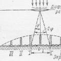
Rice. 260. Scheme of an acoustic relay.
The diagram of the simplest version of such an electronic automaton is shown in Fig. 260. Consider it carefully. There is much, if not all, here you should be familiar. The microphone serves as a sensor for control signals. Transistors V1 and V2 form a two-stage amplifier of AF oscillations created by a microphone, and diodes V3 and V4, connected in a voltage doubling circuit, are a rectifier of these oscillations. The V5 transistor cascade with an electromagnetic relay in the collector circuit and a storage capacitor in the base circuit is an electronic relay. An incandescent lamp connected to the power supply by contacts K1.1 of the relay symbolizes the executive (control) circuit.
In general, the machine works like this. While the room where the microphone is installed is relatively quiet, the transistor V5 of the electronic relay is practically closed, the contacts K1.1 of the relay are open in series, the lamp of the executive circuit does not light up. This is the initial standby mode of the machine. When an audio signal appears, such as noise or loud conversation, the audio frequency oscillations created by the microphone are amplified by transistors V1 and then rectified by diodes V3, V4. The diodes are turned on so that the voltage rectified by them enters the base of the transistor in negative polarity and simultaneously charges the storage capacitor.
If the sound signal is strong enough and the storage capacitor is charged to voltage, then the collector current of the transistor V5 will increase so much that the relay will work and its contacts K1.1 turn on the executive circuit - the signal lamp will light up. The executive circuit will be turned on as long as the same or slightly higher negative voltage is maintained on the storage capacitor and on the base of the V5 transistor.As soon as the noise or conversation in front of the microphone stops, the storage capacitor is almost completely discharged through the emitter junction of the transistor, the collector current will decrease to the original state, the relay will release, and its contacts, opening, will de-energize the executive circuit.
A trimmer resistor can change (like a volume control) the voltage of the signal coming from the microphone to the input of the AF amplifier, and thereby adjust the sensitivity of the acoustic relay.
The microphone function can be performed by a subscriber loudspeaker or a telephone capsule. The static current transfer coefficient of the transistors must be at least 30. The electromagnetic relay can be of the type, RKN with an operating current up to. The voltage of the power supply must be 25-30% higher than the operating voltage of the selected electromagnetic relay. Calculate the resistance and power dissipation of the resistor, depending on the signal lamp used, yourself.
When starting to establish and test the acoustic machine, put the trimming resistor engine in the lower (according to the diagram) position and select the resistor to set the current in the collector circuit of the transistor. It must be less than the drop-out current of the electromagnetic relay. Then, in parallel with the resistor, connect another resistor with a resistance of 15-20 kOhm. In this case, the collector current of the transistor should increase sharply, and the relay should work. Remove this resistor - the collector current should decrease to its original value, the relay should release the armature, and the lamp of the executive circuit should go out. So you will check the functionality of the machine's electronic relay.
Set collector currents of transistors V1 and V2 by selecting resistors.
Then set the resistor slider to the upper (according to the diagram) position and say quietly in front of the microphone a lingering sound "a-a-a", the machine will work and turn on the executive circuit. He should react even to a quiet conversation in front of a microphone, to a clap of his hands.
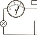
Do this experience. In parallel with the capacitor, connect a second electrolytic capacitor with a capacity of 6-10 V. In the collector circuit of the V5 transistor, turn on the milliammeter and, following its arrow, clap your hands. What happened? The collector current increased, but the electromagnetic relay did not operate. Clap your hands 5-10 times in a row. With each pop, the collector current increases and, finally, the relay picks up and turns on the executive circuit. If the sound signals are stopped, then after a while the current in the collector circuit of the transistor will decrease to the initial one, the relay will release and turn off the executive circuit.
What does this experience tell us? The electromagnetic relay of the machine began to work and release with a time delay. This is explained by the fact that now it takes more time both to charge the storage capacitor and to discharge it. The conclusion suggests itself: by selecting the capacity of the storage capacitor, it is possible to regulate the on and off times of the executive circuit.
Where and how can such an acoustic relay be used? For example, use it as a "Hush" machine. For this, the signal lamp of the executive circuit must be placed in a box, one of the walls of which is made of frosted glass, and the inscription "Hush" is written on it. As soon as the noise level or the volume of the conversation in the room exceeds a certain limit set by the trimming resistor, the light board will immediately react to it. Or, say, you can install an automatic machine along with a small-sized microphone on a self-propelled model or toy, and include its microelectric motor in the executive circuit instead of an incandescent signal lamp. A few hand claps or a voice command - and the model begins to move forward. And how? Think!
The next example of automation ...
Acoustic switch diagram
Getting into the dark, it is not always possible to immediately find the light switch, especially if it is far from the door. A similar situation can be, in the case of leaving the room, when we turned off the lighting and then have to go to the exit by touch. An acoustic switch of the circuit and design of which are discussed in this article can save you from problems.
The circuit breaker uses only an acoustic relay, for this you need to unscrew the variable resistor R2 to the minimum position.

Acoustic switch with photosensor
The photosensor is a PD263 photodiode. It is included in the circuit in the opposite direction in order to form a voltage divider together with the resistance R2. The sensitivity threshold of the photosensor ФД263 is set by the variable resistor R2.
Elements DD1.1 and DD1.2 of the K176LA7 microcircuit form a Schmitt trigger, which prevents the light machine from looping in a natural light close to the threshold. Therefore, when the photodiode is illuminated, the output of the DD1.2 element will be a logical unit, and when it is insufficiently illuminated, a logical zero.
The sensor of the acoustic relay is an electret microphone with a built-in amplifier. The microphone is connected to a two-stage amplifier assembled on bipolar transistors. The amplified audio signal from the collector of the second transistor is fed to the one-shot, assembled on the logic gates DD1.3 and DD1.4 of the same microcircuit. The latter generates single impulses with a duration of about 10 seconds, if necessary, it can be changed by selecting the resistance R12 and the capacitor C6. From the output of the one-shot, the signal goes to the field-effect transistor, which turns on the lighting lamp. The start and stop of the one-shot is carried out by the control signal from the output 4 of the DD1 element.
The automatic switch will smoothly turn on the light within 1 second if the noise threshold in the room exceeds the set value and will smoothly turn off the lighting if there are no sounds in the room after 20 seconds.

Acoustic switch on the operational amplifier
A conventional analog microphone is used as an acoustic sensor. The signal from it is amplified by the first operational amplifier. The sensitivity of the amplifier is set by the ratio of the resistances R3 and R4. The amplified acoustic signal, detected by the two detector diodes VD1 and VD2, charges the capacitor C6. After charging, the voltage on it becomes higher than on the capacitance C7, which in turn switches the comparator made on the second op-amp, as a result of which the level of a logical unit is set at its output.
The logical unit from the output of the op-amp starts the generator on the transistor VT1. The operation of the generator is synchronized with the mains supply through the second base of the same transistor. This fact makes it possible to carry out phase power control.
As soon as the voltage across the capacitor C6 drops to 2V, the voltage on DA1.2 also decreases. Because of this, the pulses that open the triac arrive with an ever-increasing phase delay, and the incandescent lamp smoothly goes out. The ratings of R5 and capacitor C6 indicated in the diagram allow you to create a delay of up to three minutes when complete silence occurs in the room.
The design of the clap switch works by clapping your hands, provided that the volume is sufficient. Thus, by cotton, the scheme turns on the lighting in the entrance (or other room) for one minute. The first design has one interesting feature to prevent looping of work, namely, the microphone turns off automatically after turning on the lighting, and turns back on only a couple of seconds after turning off the light.
The design will turn off the light not immediately after pressing the button, but with a delay of three minutes. And also turn on the light with a loud sound signal, similarly for three minutes.

The device is connected in parallel with a conventional light switch S1 and while it is closed, the lighting is on, as soon as it is opened through the R7-V4 circuit, the control electrode of the thyristor V5 begins to charge the capacitance C3. Thyristor V3 is still open, closing the rectifier bridge diagonal through itself, the lamp is on. Thyristor V5 will remain open until the capacitor C3 is charged. After 3 minutes, the capacity will be charged and the thyristor will be closed, thereby turning off the lighting.
If someone does not have time to leave the room, it is enough to clap their hands and impulses will appear on the microphone, which unlock the thyristor V3. Capacitor C3 will begin to discharge through R4 and V3, keeping it open. A pulsating voltage follows the control electrode of the fifth thyristor, which will unlock it and the lamp will light up again.
Resistance R3 adjusts the sensitivity of the microphone. This machine is designed for a load of 100 watts. If you are interested in the design, then you can take the printed circuit board drawing from No. 5 for 1980.
The circuit is used to turn on any load using any sound signal. The power of the switched load can be quite large and is determined only by the capabilities of the relay used.
The sound sensor is a regular microphone, from it, through the resistor R4, and the capacitor C1, the pulses follow to the base of VT1, opening it. To adjust the sensitivity level of the microphone, you may need to select the resistance R4. Next, the trigger, built on transistors VT2, VT3, fires. The VT4 transistor in this amateur radio design plays the role of an electronic key that controls the relay. Power supply of the circuit from any 12 volt.
Acoustic sensor selection of simple circuits |
In the first considered scheme, an acoustic-type sensor based on a piezoelectric sound emitter reacts to various vibrations in the surface against which it is leaning. Another design is based on a typical microphone.

The third circuit is very simple and does not need adjustment; its disadvantages include the following: the sensor reacts to any loud sounds, especially at low frequencies. In addition, the unstable operation of the device appears at sub-zero temperatures.
Scheme:
Taking into account all the shortcomings, the circuit was modified, as shown in the figure, and a new version of the acoustic relay was obtained. It was decided to abandon the control multivibrator, which creates interference leading to a loop, replace the powerful triac with a less powerful and more affordable triode thyristor, increase the relay sensitivity by introducing an additional amplifying stage, and introduce its adjustment, reduce the capacitance of the capacitor C5 and introduce an indication of the standby mode on LED.
Device:
The operation algorithm of the device remains the same - clap your hands, or another similar sound, and the lighting turns on for two minutes, then the light turns off automatically. The scheme of the sensor of acoustic vibrations on the operational amplifier K140UD6 is similar to the prototype previously described, and does not require explanations. Further, the signal through C5 goes to the sensitivity regulator at R5, and then, through C6, to an additional amplifier stage on the VT1 transistor. Then, through C7, the amplified signal enters the detector at VD3 and VD4. At the moment of the pop, some constant voltage appears at the output of this detector (at C8), which goes to the VT3 base and opens it. In this case, the capacitor C3 is discharged through the diode VD1 and the transistor VT3. At the inputs of the element D1.1, a logical zero is set, which is kept during the charging time of the capacitor C3 through R3 (about 2 minutes). During this time, the output of D1.1 is kept at the level of a logical unit, which goes to the VT4 base and opens it. The current flowing through this transistor turns on the thyristor VS1, which turns on the lighting lamp. As soon as C3 is charged to a single level at the output of D1.1, a logical zero is established, and the transistor VT4 will close, the unlocking current will stop, and the thyristor VS1 will also close, thus turning off the lamp. The standby indication unit is made on the D1.2 element and the VT2 transistor. While the lamp is extinguished at the output of D1.1, a logical zero acts, it is inverted by the element D1.2 and a one from its output goes to the base of VT2, which opens and turns on the LED VD2. When the lamp is turned on at the output of D1.1 one and, therefore, at the output of D1.2 is zero, the transistor VT2 is closed and the LED is off.
Setting:
The sensitivity of the device is high, with the extremely high position of the slider of the resistor R5, the device is triggered by a low sound or hand clap at a distance of 6-8 meters. During installation, free input terminals D1 must be connected to a common wire. Do not allow the network wires to pass near the input circuits of OA A1. Microphone M1 - any dynamic.
Radioconstructor No. 4 2000 p. 38
Sound relay and circuits for turning on lighting by calling a mobile phone. (10+)
Automatic lighting control - Mobile control. Sound control
Sometimes it is useful to be able to turn on the lights by calling your mobile phone. For example, in order to reach the house at night, I need to turn on the floodlight that illuminates the road. The switch, of course, is at home.
I immediately decided that I would not open and re-solder my mobile phone inside. Firstly, it's illegal. Independent modification of devices subject to mandatory certification by law is not allowed. Secondly, there is no need for such a soldering.
As with previous devices, I chose the transformerless power supply option. This immediately necessitated galvanic isolation from the telephone. For safety reasons, the mobile phone should not be directly connected to the lighting network. I settled on three variants of the scheme: acoustic, optical and transformer decoupling. All three schemes respond to a call coming to a mobile phone. Since the connection is not established, the money is not debited, so the function is completely free if you select a tariff without a monthly fee for the phone in the control system. After the call, the lighting is turned on for a fixed time. After which it goes out, but you can turn it on by calling again.
Sound relay
The first option is to use an audible relay that responds to the sound of a telephone ringing. The relay uses a computer microphone. It attaches to the phone in close proximity to the speakerphone of the phone, which emits a ringing sound. Usually this speaker is located on the back side. A telephone with an installed microphone must be soundproofed so that extraneous sounds do not cause interference. You can put it in a foam or polyethylene foam cover. Any phone with a working ring is suitable for the device. It is best to connect the phone to a charger, plug the charger into the mains and leave it like that forever. Please use the original charger so that it can work safely for a long time.
The device is connected to the power section, described on the previous page, at the points marked with the letters A, B, C, instead of the circuit on the photo relay.
Transistors: VT2- KT503, VT3- KT502. Diode VD5- KD510 or another similar low-power diode. Capacitors C4- 0.1 μF, C5- 2 μF.
Resistors: R10- 50 Ohm. This resistor must be selected in order to provide the desired sensitivity, so that the relay reliably triggers when a call is made, does not react to extraneous sounds. R11- 3 kOhm. R12- 50 Ohm. R13- 300 Ohm. R14- 50 Ohm.
All other details are as in the previous diagram.
T- a microphone from a computer. A microphone with a standard connector is connected as follows: the body - to the common wire, the pin - to the capacitor C4. If there is also a middle contact in the connector, then we simply do not connect it.
The circuit works like this. When a sound signal occurs, current pulses are fed to the base of the transistor VT2, since the base-emitter junction has one-sided conductivity so that the capacitor cannot discharge, the junction is shunted by a diode. Resistor R12 limits the current. The current pulses charge the capacitor C5 and open the transistor VT3. Capacitor C1 is charged through it. The light turns on. When the sound disappears, capacitor C1 is discharged until the lighting is turned off.