Resistors can be connected to each other in two main ways: in series and in parallel. A mixed connection of resistors is a combination of both.
Combinations of any resistor connections can be reduced to one resistor, the calculation of the resistance of which (R) we will now deal with.
Let's calculate the total resistance of such a circuit (Figure 1). For this we need Ohm's law - I = U / R and Kirchhoff's law - I = I 1 + I 2 + .. In
With this in mind, we have:
- I = U / R
- I 1 = U / R 1
- I 2 = U / R 2
- In = U / Rn
- U / R = U / R 1 + U / R 2 + ... U / Rn
- 1 / R = 1 / R 1 + 1 / R 2 + ... 1 / Rn
The last formula is the basic one for calculating the resistance of a circuit of resistors connected in parallel. For two resistors, it can be written more conveniently: R = (R 1 * R 2) / (R 1 + R 2).
From this it follows that in the case of parallel connection of two resistors of the same value (R 1 = R 2), their total resistance will be half that of any of them. This is good to remember.
 Using the laws already mentioned for a chain of series-connected resistors (Figure 2), we can write:
- U = I * R
- I = I 1 = I 2 = ... In
- U = U 1 + U 2 + ... Un
- I * R = I * R 1 + I * R 2 + ... I * Rn
- R = R 1 + R 2 + ... Rn
That is, the total resistance of the resistors in series connection is equal to the sum of their resistances.
Such a connection can always be thought of as a combination of serial and parallel connections (Fig. 3).

In this case, the total resistance of the circuit is calculated in stages. In the given example, we calculate:
- series resistance of resistors Rpos = R 1 + R 2
- parallel connection R = (Rpos * R 3) / (Rpos + R 3)
Of course, there may be more complex options, but the methodology for calculating their resistance is the same.
A few words about when it becomes necessary to connect resistors in one way or another:
- Lack of "at hand" resistor of the required rating. It should be remembered that the errors of the resistors will add up.
For example, for Figure 3.a, if the actual error of R 1 is + 10%, and R 2 has + 15%, then for R, it will be + 25%.
Here you should pay attention to the sign, that is, for -10% and + 15%, the result will be + 5%.
- The need to get more power.
Here it should be borne in mind that with the same resistance values and powers of the resistors being connected, both in series and in parallel connection, the total power will be equal to the sum of the powers.
You can read about the power and resistor values.
© 2012-2019. All rights reserved.
All materials presented on this site are for informational purposes only and cannot be used as guidelines and normative documents.
Equivalent transformations of electrical circuits.
Determination of serial connection of elements
A series connection of elements of an electrical circuit is such a connection when the output of one element is connected to the output of another element. There are no nodes at this connection point. The next element is also connected to the output of another element, etc.
The figure below shows the series connection of four resistors.
Formulas for calculating the equivalent resistance when connecting elements in series
When the resistances are connected in series, their equivalent resistance is equal to the sum of the resistances.
R eq = ΣR i = R1 + R2 + R3 + ... + Rn
When the inductors are connected in series, their equivalent resistance is equal to the sum of the inductances (excluding mutual inductance).
L eq = ΣL i = L1 + L2 + L3 + ... + Ln
When the tanks are connected in series, the reciprocal of the equivalent capacitance is equal to the sum of the reciprocals of the capacitances.
1 / С equiv = Σ (1 / C i) = 1 / С1 + 1 / С2 + 1 / С3 + ... + 1 / Cn
Daisy chain properties
When the elements are connected in series, the same current flows through them.
According to Ohm's law and Kirchhoff's second law, the equivalent (total) voltage in the section of series-connected resistances is equal to the sum of the voltages on each element. U total = U1 + U2 + U3 + U4 = I (R1 + R2 + R3 + R4). On this principle the simplest voltage dividers are built.
Defining a parallel connection
Parallel connection of electrical elements (conductors, resistances, capacitors, inductances) is a connection in which the connected circuit elements have two common connection nodes.
Another definition: resistors are connected in parallel if they are connected to the same pair of nodes.
Graphic designation of a parallel connection diagram
The figure below shows the circuit parallel connection resistances R1, R2, R3, R4. It can be seen from the diagram that all these four resistances have two common points (connection node).

In electrical engineering, it is customary, but not strictly required, to draw wires horizontally and vertically. Therefore, the same scheme can be depicted as in the figure below. This is also a parallel connection of the same resistances.

Formula for calculating parallel connection of resistances
When connected in parallel, the reciprocal of the equivalent resistance is equal to the sum of the reciprocals of all parallel connected resistances. Equivalent conductance is equal to the sum of all parallel connected conductances electrical circuit.

For the above circuit, the equivalent resistance can be calculated using the formula:

In the particular case, when two resistances are connected in parallel:

The equivalent circuit resistance is determined by the formula:

In the case of connecting "n" equal resistances, the equivalent resistance can be calculated using the particular formula:

Mixed connection... This is a combination of serial and parallel connection of elements.

Equivalent resistance for series-parallel connection of elements:
R eq = R 1 + R 2 R 3 / (R 2 + R 3)
Complex connection... This is a connection that has three or more nodes. In complex circuits, there are resistance connections in the form of a star and a triangle.
 The formulas for transforming the resistance triangle into an equivalent three-ray star are:
![]()
Formulas for the inverse transformation of the branches of a three-pointed star into an equivalent triangle:
![]() ,
,

![]()
OPERATING MODES OF POWER SUPPLIES
There are four modes of operation of power supplies. E
Idle mode... In idle mode, the ends of the source are open: (R x = ∞).
This mode is used to measure the EMF of the source. Idling mode parameters: I х = 0; R x = ∞; U x = E; (U x = E-Ir; r = 0; U x = E)
Mode short circuit ... In the short-circuit mode, the ends of the source are short-circuited: (R to = 0).
Nominal mode... This is the mode of operation of the power supply at rated current and voltage. The rated values of current and voltage are given in the passport of the power source.
Agreed mode... This is the operating mode of the power supply with maximum power P = P max. This is possible provided that R nn = R nsh. Power formula for the matched mode.
V electrical circuits elements can be connected according to various schemes, including they have a serial and parallel connection.
Serial connection
With this connection, the conductors are connected to each other in series, that is, the beginning of one conductor will be connected to the end of the other. The main feature of this connection is that all conductors belong to one wire, there are no branches. The same electrical current will flow through each of the conductors. But the total voltage on the conductors will be equal to the combined voltages on each of them.
Consider a number of resistors in series. Since there are no branches, the amount of charge passing through one conductor will be equal to the amount of charge passing through the other conductor. The currents on all conductors will be the same. This is the main feature of this compound.
This connection can be viewed differently. All resistors can be replaced with one equivalent resistor.
The current across the equivalent resistor will match the total current flowing through all resistors. The equivalent total voltage will be the sum of the voltages across each resistor. This is the potential difference across the resistor.
If you use these rules and Ohm's law, which is suitable for each resistor, you can prove that the resistance of the equivalent common resistor will be equal to the sum of the resistances. The third rule will be a consequence of the first two rules.
Application
A serial connection is used when it is necessary to purposefully turn on or off any device, the switch is connected to it in a sequential manner. For example, an electric bell will only ring when it is connected in series with a source and a button. According to the first rule, if there is no electric current on at least one of the conductors, then it will not be on the other conductors either. Conversely, if there is current on at least one conductor, then it will be on all other conductors. Also works pocket flashlight, which contains a button, a battery and a light bulb. All these elements must be connected in series, as it is necessary for the flashlight to shine when the button is pressed.
Sometimes a serial connection does not lead to the desired goals. For example, in an apartment where there are many chandeliers, bulbs and other devices, all lamps and devices should not be connected in series, since it is never necessary to simultaneously turn on the light in each room of the apartment. For this, the serial and parallel connection is considered separately, and a parallel view of the circuit is used to connect the lighting devices in the apartment.
Parallel connection
In this type of circuit, all conductors are connected in parallel with each other. All the beginnings of the conductors are combined into one point, and all the ends are also connected together. Consider a number of homogeneous conductors (resistors) connected in parallel.

This type of connection is branched. Each branch contains one resistor. The electric current, having reached the branching point, is divided into each resistor, and will be equal to the sum of the currents across all resistances. The voltage across all elements connected in parallel is the same.
All resistors can be replaced with one equivalent resistor. If you use Ohm's law, you can get an expression for resistance. If, with a series connection, the resistances were added, then with a parallel connection, the values opposite to them will be added, as written in the formula above.
Application
If we consider the connections in a domestic environment, then in the apartment lighting lamps, chandeliers should be connected in parallel. If you connect them in series, then when you turn on one light bulb, we turn on all the others. With a parallel connection, we can, by adding a corresponding switch to each of the branches, turn on the corresponding light bulb as we wish. Moreover, such switching on of one lamp does not affect the rest of the lamps.
All electrical household appliances in the apartment are connected in parallel to a 220 V network and connected to a switchboard. In other words, parallel connection is used when it is necessary to connect electrical devices independently of each other. Serial and parallel connections have their own characteristics. There are also mixed compounds.
Work current
The series and parallel connection, discussed earlier, was valid for the values of voltage, resistance and current, which are the main ones. The work of the current is determined by the formula:
A = I x U x t, where A- current work, t- time of flow along the conductor.
To determine the operation with a serial connection scheme, it is necessary to replace the voltage in the original expression. We get:
A = I x (U1 + U2) x t
We open the brackets and we find that in the whole scheme the work is determined by the sum at each load.
In the same way, we consider a parallel connection scheme. Only we no longer change the voltage, but the current strength. The result is:
A = A1 + A2
Power current
When considering the formula for the power of a circuit section, it is again necessary to use the formula:
P = U x I
After similar reasoning, the result is that the serial and parallel connection can be determined by the following power formula:
P = P1 + P2
In other words, for any circuit, the total power is equal to the sum of all capacities in the circuit. This can explain that it is not recommended to turn on several powerful electrical devices in the apartment at once, since the wiring may not withstand such power.
The influence of the connection scheme on the New Year's garland
After the burnout of one lamp in the garland, you can determine the type of connection diagram. If the circuit is sequential, then not a single light bulb will light, since a burned out light bulb breaks the common circuit. To find out which light bulb burned out, you need to check everything. Next, replace the faulty lamp, the garland will function.

When using a parallel connection scheme, the garland will continue to work even if one or more lamps are burned out, since the circuit is not completely broken, but only one small parallel section. To restore such a garland, it is enough to see which lamps are not lit and replace them.
Series and parallel connection for capacitors

With a sequential scheme, the following picture arises: charges from the positive pole of the power source go only to the outer plates of the extreme capacitors. between them transfer charge along the circuit. This explains the appearance on all plates of equal charges with different signs. Based on this, the charge of any capacitor connected in series can be expressed by the following formula:
q total = q1 = q2 = q3
To determine the voltage across any capacitor, you need the formula:
Where C is the capacity. The total voltage is expressed by the same law that applies to resistances. Therefore, we obtain the capacity formula:
С = q / (U1 + U2 + U3)
To make this formula simpler, you can flip the fractions and replace the ratio of the potential difference to the capacity charge. As a result, we get:
1 / C = 1 / C1 + 1 / C2 + 1 / C3
Parallel connection of capacitors is calculated a little differently.

The total charge is calculated as the sum of all charges accumulated on the plates of all capacitors. And the voltage value is also calculated by general laws... In this regard, the formula for the total capacity for a parallel connection scheme looks like this:
С = (q1 + q2 + q3) / U
This value is calculated as the sum of each device in the circuit:
C = C1 + C2 + C3
Mixed connection of conductors
In an electrical circuit, sections of the circuit can have both serial and parallel connections, intertwined with each other. But all the laws considered above for certain types of compounds are still valid, and are used in stages.

First you need to mentally decompose the circuit into separate parts. For a better presentation, it is drawn on paper. Let's consider our example according to the scheme shown above.
It is most convenient to depict it, starting with the points B and V... They are placed at some distance between themselves and from the edge of the sheet of paper. From the left side to the point B one wire is connected, and two wires leave on the right. Point V on the contrary, it has two branches on the left, and one wire leaves after the point.
Next, you need to depict the space between the points. Along the upper conductor there are 3 resistances with conventional values 2, 3, 4. At the bottom there will be a current with index 5. The first 3 resistances are included in the circuit in series, and the fifth resistor is connected in parallel.
The other two resistances (first and sixth) are connected in series with the section we are considering B-C... Therefore, we supplement the scheme with 2 rectangles on the sides of the selected points.
Now we use the formula for calculating resistance:
- The first formula for a sequential type of connection.
- Further, for a parallel circuit.
- And finally for a consistent scheme.
In a similar way, any complex circuit can be decomposed into separate circuits, including connections not only of conductors in the form of resistances, but also of capacitors. To learn how to master the calculation techniques for different types of schemes, you need to practice in practice by completing several tasks.
1 mΩ = 0.001 Ω. 1 kOhm = 1,000 = 10³ Ohm. 1 MΩ = 1,000,000 = 10⁶ Ohm.
The equivalent resistance R eq of a group of resistors connected in parallel is the reciprocal of the sum of the values inversely proportional to the resistances of these resistors.

In other words, the conductivity G resistors connected in parallel is equal to the sum of the conductances of these resistors:
This formula is for R eq and is used in this calculator for calculations. For example, the total resistance of three 10, 15 and 20 ohm resistors connected in parallel is 4.62 ohms:

If only two resistors are connected in parallel, the formula is simplified:

![]()
If there is n parallel-connected identical resistors R, then their equivalent resistance will be
Note that the total resistance of a group of any number of resistors connected in parallel will always be less than the smallest resistance of the resistor in the group, and adding a new resistor will always lead to a decrease in the equivalent resistance.
Note also that all resistors connected in parallel are at the same voltage. However, the currents flowing through individual resistors are different and depend on their resistance. The total current through a group of resistors is equal to the sum of the currents in the individual resistors.
When connecting several resistors in parallel, always consider their tolerances and power dissipation.
Application examples for parallel connection of resistors
One example of parallel connection of resistors is a shunt in an instrument for measuring currents that are too large to be directly measured by an instrument designed to measure small currents or voltages. To measure the current, a resistor with a very small, precisely known resistance, made of a material with stable characteristics, is connected in parallel with a galvanometer or an electronic device that measures voltage. This resistor is called a shunt. The measured current flows through the shunt. As a result, a small voltage drops across it, which is measured with a voltmeter. Since the voltage drop is proportional to the current flowing through the shunt with a known and accurate resistance, a voltmeter connected in parallel with the shunt can be scaled directly in current units (amperes).

Parallel and series circuits are often used to obtain accurate resistance, or if a resistor of the required resistance is not available or is too expensive if purchased in small quantities for mass production. For example, if a device contains many 20K resistors and only one 10K resistor is needed. Of course, it's not hard to find a 10k resistor. However, for mass production it is sometimes better to put two 20K resistors in parallel to get the required 10K. This will lead to lower costs printed circuit board since it will be reduced Wholesale price components, as well as the cost of installation, since the number of standard sizes of elements that must be installed on the board by the automatic component installation will be reduced.
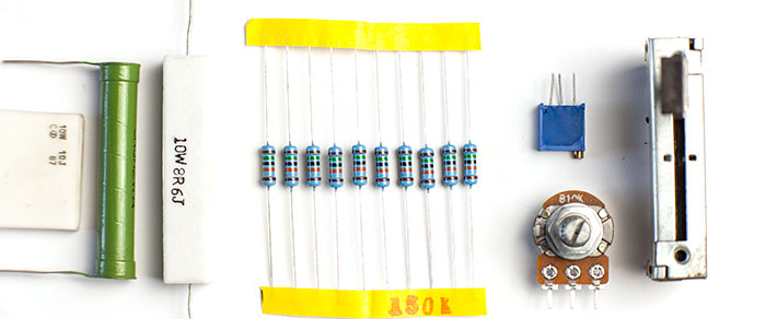
Each electrical circuit contains a resistor that resists electrical current. Resistors are of two types: fixed and variable. During the development of any electrical circuit and repair of electronic products, it is often necessary to use a resistor with the required rating.
Although the resistors are available in different ratings, it may happen that it will not be possible to find the required one, or in general no element will be able to provide the required indicator.
The solution to this problem can be the use of serial and parallel connections. After reading this article, you will learn about the features of the calculation and selection of various resistance ratings.
Parallel connection: general information
 Often, in the manufacture of a device, resistors are used, which are connected in accordance with a series circuit. The effect of using this type of assembly is reduced to an increase in the total resistance of the circuit. For this option of connecting the elements, the resistance they create is calculated as the sum of the denominations. If the assembly of parts is carried out in parallel, then here need to calculate resistance using the formulas below.
The parallel connection scheme is resorted to in a situation where the task is to reduce the total resistance, and, in addition, increase the power for a group of elements connected in parallel, which should be greater than when they are separately connected.
Resistance calculation
 In the case of connecting parts with each other, using a parallel circuit to calculate the total resistance, the following formula will be used:
R (total) = 1 / (1 / R1 + 1 / R2 + 1 / R3 + 1 / Rn).
- R1-R3 and Rn are resistors connected in parallel.
 Moreover, if the circuit is created on the basis of only two elements, then the following formula should be used to determine the total nominal resistance:
R (total) = R1 * R2 / R1 + R2.
- R (total) - total resistance;
- R1 and R2 are resistors connected in parallel.
Video: An example of calculating resistance
Universal calculation scheme With regard to radio engineering, attention should be paid to one important rule: if the elements connected to each other in a parallel circuit have the same indicator, then to calculate the total value, the total value must be divided by the number of connected nodes:
- R (total) - total resistance value;
- R is the value of the resistor connected in parallel;
- n is the number of connected nodes.
Particular attention should be paid to the fact that the final resistance index in the case of using a parallel connection will definitely be less in comparison with the rating of any element connected to the circuit.
Calculation example
 For greater clarity, you can consider the following example: let's say we have three resistors, whose values are respectively equal to 100, 150 and 30 ohms. If we use the first formula to determine the total denomination, we get the following:
R (total) = 1 / (1/100 + 1/150 + 1/30) =
1 / (0.01 + 0.007 + 0.03) = 1 / 0.047 = 21.28 Ohm.
If you perform simple calculations, you can get the following: for a circuit that includes three parts, where the smallest resistance is 30 ohms, the resulting value of the nominal will be 21.28 ohms. This indicator will be less than the minimum value of the nominal value in the chain by almost 30%.
Important nuances
 Usually for resistors, parallel connection is used when the task is to create a resistance of higher power. To solve it, resistors will be required, which must have equal resistance and power. With this option the total power can be determined as follows: the power of one element must be multiplied with the total number of all resistors that make up the circuit, connected to each other in accordance with parallel circuit.
Say, if we use five resistors, whose nominal value is 100 Ohms, and the power of each is 1 W, which are connected to each other in accordance with a parallel circuit, then the total resistance indicator will be 20 Ohms, and the power will be 5 W.
If we take the same resistors, but connect them in accordance with a series circuit, then the final power will be 5 W, and the total rating will be 500 Ohms.
Video: Correct LED connection
The parallel circuit for connecting resistors is very popular for the reason that the task often arises of creating such a rating that cannot be achieved with a simple parallel connection. Wherein the procedure for calculating this parameter is rather complicated where it is necessary to take into account different parameters.
Here, an important role is assigned not only to the number of connected elements, but also to the operating parameters of the resistors - first of all, resistance and power. If one of the connected elements has an unsuitable indicator, then this will not effectively solve the problem of creating the required rating in the circuit.