), however, such switches have one serious drawback - lighting control, i.e. it can be turned on and off only from one place. Imagine a situation that everyone faced, for example: you go home, turn on the light in the hallway, take off your outerwear and walk into the room, but stop, the light in the hallway needs to be turned off, and having done this, you will have to leave the hallway in the dark, the same applies to long ones. corridors or flights of stairs. In such situations, it becomes necessary to control the lighting from two places, it is for the solution of such tasks that the so-called pass-through switches are intended.
In this article, we will consider various options for connecting pass-through switches to control lighting from 2, 3 or more locations.
NOTE: Before connecting pass-through switch it is necessary to check with the diagram given in his passport and / or the diagram printed on the back of the switch itself (if any).
2. Lighting control from two places:
To organize lighting control from two places, it is necessary to use 2 pass-through switches. Below are the connection diagrams for two single-key (single) and two two-key (double) pass-through switches.
2.1 Connection of two pass-through one-button switches.
To begin with, let's figure out what a single-key pass-through switch is, outwardly it is practically indistinguishable from a conventional one-key switch, however, unlike the latter, it has not 2, but 3 terminals for connecting wires, in addition, two triangles located vertically, one can be present on the pass-through switch key above the other and pointing their vertices up and down, respectively:
As you can see in the picture above, on the reverse side of the pass-through switch, as a rule, there is its circuit, while the terminals for connecting the wires to the switch can have different alphabetic, digital or symbolic designations, for example, it can be: "L, 1,2"; or "1,2,3"; also, the designations can be arrow, in this case one arrow points to the inside of the switch, and the other two arrows point to the outside.
One-key pass-through switches are connected with three-core cables (as shown in the picture above), for example, with a VVG 3x1.5 cable - if the internal wiring is made of copper, or with an AVVG 3x2.5 cable - if the internal wiring is made of aluminum.
Pass-through switch connection diagram:
The connection of wires to single-key pass-through switches is performed as follows:
By connecting 2 pass-through switches in this way, you can organize lighting control from two places. How exactly such a scheme works can be seen in the GIF animation below:
As you can see in this diagram, unlike conventional switches that simply break (turn off) electrical circuit(see article :) pass-through switches perform switching from one circuit to another, therefore, often pass-through switches are called pass-through switches.
2.2 Connection of two two-key pass-through switches.
A double pass-through switch consists of two single-key pass-through switches combined in one housing, respectively, such a switch will have 6 terminals for connecting wires, therefore, the connection of the pass-through two-button switch must be done with two three-core cables.
Wiring diagram of a two-key 2-point pass-through switch:
Connect the wires to the double pass switches as follows:
3. Lighting control from three or more locations
If it is necessary to connect pass-through switches to control lighting from 3 places or more, as a third, fourth, etc. switches must be connected cross or, as they are also called, intermediate switches (switches), they got this name because these switches must be included in the circuit between two pass-through switches.
One-button cross switches have 4 terminals for connecting wires, two-button switches, respectively, have 8 terminals, etc. On the keys of intermediate switches, as well as on the passage switches, two triangles can be applied, however, unlike the passage switches, they are not vertically located relative to each other, but horizontally:
The cross switch is connected according to one of the following diagrams.
The wiring diagram for 3-pass switches (2-pass and one cross) for lighting control from three places will look like this:
In turn, the connection of wires to the switches with such a scheme will be performed as follows (note: before connecting, you must check the diagram located on the back of the switch or given in its passport):
This scheme connecting pass-through switches together with a cross allows you to organize lighting control from three places. The principle of operation of such a scheme can be studied by the GIF animation below:

Pass-through switch diagrams allow switching on and off lighting from two or more different places of their installation. In some cases, this is not only convenient, but also very necessary.
For example, the room has a long corridor. It is naturally illuminated. Turning on the light at the beginning, and having this very circuit breaker connection, you do not have to return again to disconnect, but you can do this with the second switch, which is installed at the other end of the corridor. Very often, such schemes are also used to control staircase lighting.
Which is better to use: pass-through switches or bistable relays? Answer .
How to properly connect pass-through switches for independent lighting control from two places.
Let's take a closer look at this wiring diagram consisting of two pass-through switches... It requires two switches (also called "pass-through"), each with three contacts and two switching positions. Moreover, the switching mode should be "flip-over", that is - one contact is common to the other two. In one position, he is closed with one of them, and in another position, naturally, with the other. Therefore, the general closure of all three contacts is completely excluded.
Wiring diagram of a pass-through switch for controlling a luminaire from 2 places

Pass-through switch for three contacts and two positions (there is a common contact at the top)
Explanations for the diagrams
Now let's deal with the drawn diagrams. Both circuits consist of the pass-through switches themselves, a lamp and connecting wires (during installation, these will be two, three and four-core cables). The first diagram shows wiring diagram of the pass-through switch with control from two different locations.
As you can see, one wire (in our case it is zero) goes from the power supply to the junction box and from it to the lamp. The other (phase wire), after the box, is connected to the common contact of one of the switches. Two changeover contacts of one breaker are connected to two contacts of the second breaker (via the box). Well, from the common contact of the second switch, the phase is fed to the second contact of the lamp.
As for the installation of this circuit itself: they are put in their installation places pass-through switches from which three-core cables are taken out. Luminaires are mounted that are connected in parallel and from which a two-core cable eventually comes out.
Further, in the most suitable place, a junction box is installed (taking into account the minimum cable length and the convenient location of this box itself). The cable is then inserted into it from the lamps, power supply and the walk-through switches themselves. This box is made between each other as shown in the diagram.
Wiring diagram of a pass-through switch for controlling a luminaire from 3 places
How to control lighting from three locations
Connection diagram of the pass-through switch with control from three places not much different from the previous one ( general principle work is the same). It has added another pass-through switch, which is slightly different from the previous ones. As you can see from the diagram, this coupled switch... That is, when one key is pressed, two contacts are simultaneously flipped, electrically independent of each other. In addition, as you should have noticed, a four-wire cable comes out of it.
Wiring diagrams of pass-through switches of this type are good in that they are relatively simple in their design (no additional components are required). But they are limited by the number of such control places.
The task of independent lighting control from two places can also be solved using special impulse relays and.
To increase the comfort and convenience in the operation of lighting devices, a pass-through switch is used: the connection diagram clearly displays the principle of operation of the switching device. With its help, you can control the lighting of the room from any point. The design features and rules for installing the product are described in detail in this article.
Pass-through switches are used to organize the control of luminaires from several locations
Pass-through switches are designed to turn on and off lighting from different ends of the room or staircase. This means that you can turn on the light, for example, when entering a room, and turn it off - in another part of it. This principle of operation allows you to significantly save energy.

Pass-through switch on appearance does not differ from the usual. Its front movable panel also shows up and down arrows. A conventional switch has one input and one output. In contrast, a pass-through device has one input and two outputs. This indicates that the current is not interrupted here, but is redirected to any of the outputs.
How to connect an outlet with your own hands. Description of preparatory measures and installation technology. Electricity Handling Rules
If lighting control is planned from a larger number of places, additional cross switches are introduced into the general scheme, which are connected according to the above principle.
Each pass-through switch has a three-wire cable, and the crossover has a four-wire cable. All wires used for connection must be of the same cross section. Switches that can operate at 6.10 and 16A normal currents must have the same rating. You can clearly see the connection diagram of the pass-through switches from 3 places on specialized sites on the Internet.

Wiring diagram of a two-key pass-through switch
With the help of pass-through switches, you can control not only one luminaire, but also a group of several lighting fixtures. To do this, connect the checkpoints two-button switches... Each of them has six contacts. Common wires are determined in the same way as for conventional devices, but more wires need to ring.
The difference between the connection diagram of the double pass-through switch is that more wires are used here. The phase is applied to both inputs of the first switch. From the two inputs of the second switch, wires for two lamps should go out. In the case of organizing lighting control from three or more points, two cross switches should be installed for each of them, since they are produced only with one-key.

In this case, according to the principle of connecting double pass switches with cross switches, the first pair of contacts should be connected to one cross, and the second - to the other. If necessary, the devices are connected to each other. The output of both cross switches must be connected to the last two-key jumper.
Famous manufacturers of pass-through switches
The Legrand company occupies a leading position in the electrical goods market. The demand for Legrand pass-through switches is due to the high quality of products, ease of installation, convenience in further operation, stylish design and flexible pricing policy... The only drawback is the need to adjust the mounting location. If it does not match the product, difficulties may arise during its installation, which is carried out according to the connection diagram of the Legrand pass-through switch.

Legrand's subsidiary is the Chinese company Lezard. However, only a stylish design remained from the original brand. The build quality is much lower due to the low cost of the product.
One of the leading domestic manufacturers of electrical goods is Wessen, which is part of Schneider Electric. All products are manufactured according to the latest technology on modern foreign equipment and meet European quality standards. The models have a versatile stylish design that allows each element to fit into any room interior. Distinctive feature of Wessen circuit breakers is the possibility of replacing the decorative frame without dismantling the device.
Another equally well-known manufacturer is the Turkish company Viko. Products are characterized by high quality workmanship, reliability and durability, meet the requirements of electrical safety and European quality standards. In the manufacture of the device case, a fireproof durable plastic is used, which is designed for a large number of operating cycles.

Turkish brand Makel offers quality, reliable, safe and stylish products. Due to the possibility of connecting a loop without the need to use the junction box, the installation of the switches becomes simpler, and further operation becomes comfortable and safe.
Popular range of pass-through switches
Legrand walk-through switches from the Velena series are distinguished by their stylish design and a variety of color variations. Here are one and two-key products that have a dust and moisture protection layer. You can buy a switch from 300 rubles.
The Celiane series includes products with circular keys inscribed in a square. They can be contactless with levers or silent. The cost of switches starts at 700 rubles. The lineup Exclusive Celiane is represented by a limited number of handcrafted switches in marble, bamboo, porcelain, gold, myrtle and other materials. Frames are made exclusively to order. The price for the product starts from 5.9 thousand rubles.

The most popular series of switches from Lezard are Demet, Mira and Deriy. Here are products made of non-combustible polycarbonate that meets the requirements of electrical safety. The conductive elements are made of phosphor bronze, which is characterized by high conductivity and low heating. You can buy a single-key switch through from 125 rubles.
The Wessen W 59 Frame series uses a modular principle, allowing 1 to 4 units to be mounted in one frame horizontally or vertically. The price of the product is 140 rubles. Single and double pass-through switches from the Asfora series are distinguished by a simple design, but high quality performance, which can be bought for 450 rubles.
Among the popular series of the Makel company are Defne and Makel Mimoza. The body of the devices is made of high quality plastic, equipped with an internal reliable mechanism. The cost of products starts from 150 rubles.

The principle of operation and installation of switching devices do not present significant difficulties. It is necessary to first study the connection diagram and follow the recommendations of the electrical safety rules, which will make it possible to carry out a reliable and safe installation of devices, thereby ensuring convenient and comfortable control of lighting devices in the house.
How to connect a pass-through switch: video connection diagrams
As an electrical engineer, I only discovered the existence of a walk-through switch when building a house. It seemed to me undignified to return to the hallway after turning on the lighting in the living room to turn off the lamp at the front door.
In the end, I applied them in four cases. It's funny, but a few years after the completion of the construction of the house, it dawned on me that it had to be done three more times!
Now, based on the experience gained, I strongly recommend that you familiarize yourself with the wonderful properties and possibilities of a simple and useful device.
 Pass-through switch: what is this about?
In academic terms, a walk-through switch is a device that allows independent control of lighting from different locations. For clarity, you can play: one person is trying to turn on the lamp, and the other is trying to turn it off. In doing so, they control lighting from different locations. It will turn out to be a fun disco with blinking lamps, but it is impossible to win!
In practice, such devices are used in order to turn on the lighting at one point, pass a certain area with comfort and turn off the light at another point, without going back. Hence the name - pass or marching switch. In this case, the whole trick lies in the device diagram.
 Let's compare a conventional switch with a pass-through
 As you can see, when a third contact is added to a conventional switch, it becomes a straight through. Moreover, from the point of view of circuitry, it is correct to call such a device a switch, since the circuit never breaks and the switching contact, at any position of the key, is connected to one of the output contacts.
Practical examples
It is far from always obvious where exactly the control of luminaires should be provided. The task is simplified by looking at practical examples.
 Lighting control between garage and home
 In this case, marching switches are used to provide lighting for the path between the garage and the house:
- garage lighting control;
- lamp above the door to the garage;
- illuminated path;
Thus, you can turn on the light from the house, walk comfortably through the illuminated area and turn off the lamps already in the garage, or vice versa. In this specific example there are two more possibilities:
- working in the yard, you can turn on the lighting;
- if you are waiting for guests, you can control the light outside from home.
I added a light sensor to the lighting circuit of the local area, and the lamps in the yard turn on automatically at nightfall, if necessary. Read about the sensor application in a separate article.
 Pass-through switches control the lighting in the vestibule
 The house is not very comfortable in the dark vestibule, and marching switches are also installed to control its lighting:
- porch lighting control;
- lamp on the wall;
- lighting control in the hallway.
Now we close the front door, turn on the lamps in the hallway, and turn off the lights on the street and in the vestibule. To control the light on the way from the hallway, it would be necessary to install pass-through switches in all three rooms on the first floor. In order not to do this, the lighting in the hallway is turned off by a timer. Read about its installation in a separate article.
 We go up the illuminated stairs and turn off the light
 For staircase lighting, marching switches are a must:
- lighting control in the living room on the ground floor;
- three lamps on the staircase;
- lighting control on the second floor site.
The platform on the second floor is small, so after turning on the lights in one of the rooms, you can go back and turn off the lamps on the stairs. This did not suit me, and a timer was added to the switch wiring diagram. Now it can be turned off immediately, and the lighting will turn off the timer after 2 minutes.
 We descend into the basement along the illuminated staircase
 We also go down to the ground floor along the illuminated staircase:
- lighting control at the entrance to the basement;
- lighting control in the basement.
In the basement, everything is a little simpler: here, in one block, you can turn on the lamp in any room. Thus, you can first turn on the light in one of the rooms, and then turn off the staircase lighting.
 An example of installing walk-through switches in the bedroom
 Here is a blatant example of hindsight: there are no walk-through switches in the bedroom! You have to turn off the lights at the door, and then move in complete darkness by touch, risking bumping into the corner of the bed. You can, of course, turn on the sconce, and then return to the entrance again and turn off the general light. The correct way is to do this:
- lighting control at the front door;
- sconces at the bedside tables;
- alternatively, you can use the lamps opposite the bed;
- lighting control at the headboard.
Roughly the same should have been done in the other 2 bedrooms. I hope these examples will inspire you to make the right decisions.
Varieties of cross and loop switches
Let's take a closer look at the subject of our interest. First, we will study the existing options, and then we will learn how to connect them to the electrical wiring.
 The main types of pass-through switches
 In appearance, rocker switches differ in color and shape, and they are also:
- hidden or open installation;
- one-key, two-key, three-key;
- with or without backlight;
- the special character on the keys may or may not be present.
 Internal diagrams of pass-through switches
 Considering the internal scheme, we can talk about the following types:
- One-key pass-through switch. It is used most often as the first and last device in the case of 2 or more control places.
- Pass-through switch with two keys. A double fixture is used for the same purpose to control lighting using 2 groups of luminaires.
- 3-key pass-through switch. Used for the same purpose to control three groups of luminaires.
- One-key crossover or rocker switch. It is used as an intermediate device in a chain of three or more locations.
- Two-gang cross switch. It is used as a middle device in a chain of 3, 4 or more control points for two groups of luminaires.
As follows from the given illustration, in the pass-through switch, the input terminal is connected to one of the output terminals when the key is pressed. In crossover - the conductors connected to the input and output are swapped when the position of the key is changed.
No point in this moment worry about the variety of internal circuits. Firstly, only a single pass-through switch is most often in demand. Secondly, you may need something else, and this will become clear from the specific options for connecting devices.
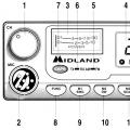
 Rear view of pass-through switches of different types
 The photo shows a rear view of the wiring accessories. Now you will be able to choose and purchase the required model yourself. Unfortunately, not all manufacturers indicate the pin marking on the device case. If it is absent, you will have to use a multimeter to find out the location of the product terminals.
Connection diagrams of pass-through switches
The way the cruise switches are disconnected is determined by the specific conditions of use. In several cases, we will consider 2 options for the connection image. The first of them is easier to understand, and it is sufficient when installing devices in the case of existing electrical wiring. Another option takes into account the requirement to lay the cable using junction boxes, which can actually be done in a new building or when replacing wiring.
Standard 2-point installation
The option of controlling one or more parallel-connected lamps from two locations is the most demanded and simpler option. There are four possible combinations of the position of the keys of the two switches: in two of them the lamp is on, in the other two it is off.
 The most popular connection scheme for two pass-through switches with one luminaire
 In the example with a photo of devices in the back, the circuit is open, and the lamp does not light up. In the lower part of the illustration, the circuit is closed and the light is on. We can say that in this connection scheme, one conventional switch is replaced by two single-key pass-throughs, interconnected by a two-core cable.
 Wiring diagram for connecting two switches with a lamp
 This illustration shows the connection using a junction box. As you can see, each of the devices is connected to the box with a three-core cable.
Control schemes for one luminaire from several points
Multi-point control is necessary when driving along a long passage. For example, in a three-story house, on each floor, you can control the lighting on the stairs where necessary.
 Option to control one luminaire from three points
 A cross switch is required to realize an independent lighting control scheme from three locations. As in the previous version, they can be interconnected with a two-core cable.
 Installation of three pass-through switches using a junction box
 Now we will get acquainted with the wiring diagram, performed according to all the rules, using a distribution box. As you can see, connecting two pass-through switches to the junction box requires a three-wire cable, while a crossover requires two two-wire cables.
 Connection diagram of four pass-through switches to control one luminaire
 Using the same principle, you can build a lighting control scheme from 4 or more locations. The first and last device in the chain is the pass-through switches. Intermediate devices are cross-type.
Controlling multiple luminaires from multiple locations
There are situations where you need to control multiple luminaires from multiple locations. For example, in the bedroom it is possible to install one two-key pass-through switch at the door, and the other at the bed. Then in both places it will be possible to turn on and off both the general lighting in the room and the lamps by the bed.
 Connection diagram of two pass-through switches with two separate luminaires
 To implement such a scheme, you will need two two-key pass-through switches. In the simplest case, two two-core cables are required to connect them.
 Wiring diagram for connecting two switches with two separate luminaires
 The wiring diagram of the correct connection of a two-key pass-through switch using a junction box looks more impressive. Box required big size as it should fit eight wire connections. To connect the first pass-through switch, you will need a two-core and three-core cable, and to connect the second, two three-core cables.
 Control circuit for three independent luminaires from two points
 Theoretically, by increasing the number of 2-key switches, it is possible to independently control the illumination of 2 lamps from any number of locations. You may want to operate from two locations with three groups of bulbs in a chandelier. A circuit using a triple switch demonstrates the real possibility of such work, but a lot of cable is required.
 Control circuit for two luminaires from three locations
 This 3-position pass-through switch wiring diagram demonstrates the ability to control two separate light bulbs. Two two-key walk-through switches can be located by the bed, the third - by the bedroom door. Everywhere you can turn on and off local lighting, or a general lamp.
 Control circuit for two separate luminaires from four points
 As we have already noted, the lighting control scheme is infinitely scalable. The ability to turn on and off 2 different lights from four points can come in handy in a long hallway of a house with big amount rooms. Obviously, after considering various examples, it will not be difficult to draw up any independent lighting control scheme using one-key and other pass-through switches.
Installation of pass-through switches with existing wiring
It is likely that you will want to equip with your own hands an independent control of lamps with existing electrical wiring. In this case, it is quite difficult to provide electrical installation using a box and laying a cable 15 cm from the ceiling, because the wiring in the wall can be damaged.
In any case, you need to get a tester to detect the cable under the plaster and check its presence where you are going to do something. In addition, when performing work, you should completely de-energize the wiring in the house or apartment.
 Installing Loop Switches with Existing Wiring
 Let's consider step by step the option of lighting control from 2 points. From the given illustration it follows that the pass-through switch No. 1 can be installed instead of the existing conventional one. To mount device No. 2, you should prepare a place in the wall, which can be read about in a separate article.
The next step is to make a strobe connecting both devices. A three-core cable is laid in the seam and the wall is putty.
It can be seen from the wiring diagram that the green core of the three-core cable coming from device no. 2 should be connected to the corresponding core of the cable from the junction box to device no. 1. The connection is placed in the socket of the device No. 1 and is performed by twisting, or using a special clamp. It is better to solder the twist and wrap it with electrical tape. Do not change anything in the junction box.
Standard situation: you entered the house and turned on the light in the hallway, and then moved to the bedroom. Now you need to go back to put out the corridor light, which is not very convenient. And if the rest room is located on the second floor of a private house, then you will have to climb the stairs twice to turn off the lighting in the hallway. The connection diagram of the so-called pass-through switch will help to solve this problem, which allows you to use the control of one lamp (or a group of lamps) from 2 places.
Two-point control principle
In practice, the system works as follows:
- Entering a dark corridor, you light up a lighting fixture.
- Having moved to another room or to the second floor, you turn it off with the second switch installed in this room.
- Everyone who enters the house after you will be able to turn on the light in the hallway again and extinguish it in a convenient way at one of two points.
Note. With the same success, you can organize lighting control from 3 or even 4 different places, which will be discussed below.
Simply put, the light turns on and off at the first point, regardless of the position of the key at the second, and vice versa. The key element of the circuit is a pass-through (otherwise - marching) switch, which differs from the usual one-key switch with three contacts for connecting wiring. Two such devices must be placed in convenient places and connected to electrical network triple (three-core) cable according to the following scheme:
In fact, our devices are switches that switch the phase current in one of two directions. Switching occurs between these lines, only from different sides. In whatever position the buttons are initially, pressing any of the two keys will lead to a short circuit or an open circuit.

The photo shows that the middle contact closes to one of the extreme, there is no complete shutdown mode
Reference. Loop switches are far from new. Conventional, two-key and three-key models of products have been produced for a long time renowned manufacturers electrical equipment - Schneider Electric (Schneider Electric), Legrand (Legrand) and Lezard (Lezard). What a similar device looks like is shown in the photo.

To control a group of lamps from different rooms with the ability to turn on one or several lamps, you need to use double (two-pole) switches and connect them according to the following scheme:

- Install the pass-through switches on the plastic sockets in the required places. From each of them, route three-wire cables through the gates to the junction box.
- Inside the box, connect directly the neutral and ground contacts leading to the light bulb. Connect the phase wires from the mains and the lamp to the conductors leading to the changeover contacts of the switches.
- In the same place, dock the contacts of the double line between our buttons. This completes the installation.
Inclusion from 3 or more places
To implement such a lighting control, the shown circuit of the pass-through switch is supplemented with one more element. This is the so-called cross (otherwise - paired) switch for 4 contacts, whose installation is provided between the extreme disconnecting devices, as shown in the picture below. Its principle of operation is as follows:
- in the first position, the button directly closes both circuits;
- after switching, the lines are closed crosswise.

Note. If it is necessary to control the luminaire from 4 or more places, then a second paired switch is added to the circuit, a third, and so on ad infinitum.
It is somewhat more difficult to disconnect the devices in this case, since a four-core cable appears here for connecting a crossover device. It is better to do the wiring inside the junction box, and not in the socket boxes, while it is advisable to duplicate the colors of the wires with tags in order to avoid confusion. Available and detailed about the connection diagram is described in the video:
Common installation mistakes
At self-assembly the described schemes, the owners of apartments and private houses admit several typical mistakes, which is why the system does not work initially or fails in the near future. We list these shortcomings and the reasons that cause them:
- One of the remote switches finally breaks the circuit (as a rule, cross), the rest also stop functioning. This is a clear sign of incorrect connection of contacts, you need to check everything and connect correctly.
- One of the keyboards quickly burns out and has to be replaced frequently. Here, there is a high load from lamps on the switch contacts, designed for a maximum power of 2.2 kW (current 10 Amperes). If it cannot be reduced, you need to switch to another method of switching - using impulse relays with parallel connection of pushbutton switches.
- Periodic flashing of luminescent and LED lamps operating from pass-through switches. The reason is low-quality products with poor insulation (there is a leak) or cheap micro-lamps for night illumination built into the housings for orientation in the dark.
An important point. Serious error leading to electric shock under certain conditions - connection to a shut-off valve neutral wire instead of phase.

Push-button dimmer combined with a pass-through switch
Also, malfunctions occur when used simultaneously with dimmer pass-through two-position switches - electronic devices to adjust the brightness of the light bulbs. This happens when you are trying to assemble a circuit from cheap elements with poor quality insulation.
Conclusion
Despite the emergence of new ways of switching lighting using impulse relays and blocks remote control, the circuit with pass-through switches remains the simplest and most affordable component. There is only one drawback of the system: the keys do not have a fixed "on" and "off" position, which sometimes causes inconvenience. For example, being on the second floor of a house, you cannot see if the light on the first is turned off, and you cannot understand this by the toggle button.

Design engineer with over 8 years of experience in construction.
Graduated from the East Ukrainian National University. Vladimir Dahl with a degree in Electronic Industry Equipment in 2011.
Related entries: