Alexey OMELYANCHUK, expert
Inborn greed (in other words - thriftiness, thriftiness) does not allow even reasonable designers to design intelligent systems. It would seem that you need to connect 32 “Exit” signs to the system (one on each floor), put the required number of relay blocks - and you will be happy. For example, 8 blocks with 4 relays each. But no, because I want to save money, and therefore the project will have one relay output (fortunately, the relay "holds" 3 amperes), to which all 32 plates will be connected to one pair of wires in a long chain (the total consumption, okay, we consider acceptable - 32 * 90 mA = 2.88 A). Total length approx. 300 m (10 m between the plates). What is the ambush?
The first ambush is that most of the plates (lamps, sirens, sirens and other similar devices) have a very limited operating voltage range. For example, the popular KOP-24 device operates at voltages from 18 to 28 V. Huge range! Yes? No.
We put building block 24 V power supply (in fact, it usually outputs 27.5 V, because it contains two lead-acid batteries with a "float" voltage of 13.8 V - like in a car). Fits? Fits. Farther. The system should work in case of power failure for another 24 hours in standby mode and 3 hours in alarm mode. It is clear that the batteries are also calculated "economically", so by the end of this period the voltage at the output of the power supply will be about 20 V. Suitable? Also fits. But! There is a 2 V margin for the voltage drop across the wires.
With a consumption current of 3 amperes, the permissible wire resistance is only 0.6 ohms. We recall one of the first articles about 30% - the resistance of a single wire with a cross section of 1 mm 2 and a length of 100 m = 2 ohms. We recalculate - we get: with a cable length of 300 m, the resistance is 0.6 Ohm for a cable with a cross section of 2x16 mm 2. Such a cable can only be bent over the knee, and then a bruise can turn out. The cost of one (!) Meter of such a cable is equal to the cost of one scoreboard. Wow savings ...
Yes, and it will not work to connect such a cable to the existing scoreboards, and it will not even be easy to stretch it in the existing risers between floors.
And here we pay attention to the fact that there are plates with a noticeably wider supply voltage range, and at the same time with a significantly reduced consumption current. Usually this effect is achieved using switching power supplies, but I will not go into the technological secrets of manufacturers. It is important for us now that there are seemingly not very different devices with an allowable supply voltage range of 10-40 V and a consumption current of 20 mA. We recalculate everything anew. We will leave the power supply the same, which is customary for fire systems 24 V. The permissible voltage drop even from completely discharged batteries will already be 20 V-10 V = 10 V. The current consumption of the entire chain is 32 x 20 = 640 mA. We divide - we get: we are satisfied with the resistance of 16 ohms. This means a 2 x 0.75 cable is good! quite another matter! (fig. 1).
Now let's calculate a little more accurately. The average cable current is not 640 mA at all. This is only in the first section from the relay to the first display, the current is maximum, and then the current is less. If we consider that the displays are evenly distributed along the loop, then the average current can be considered equal to exactly half of the full, i.e. 320 mA. Fans of mathematics can figure out for themselves why this can be considered, I will explain to the rest: in the first section, current flows from 32 boards, in the next - from 31, etc. Accordingly, the voltage drop in the first section is equal to R cable * 32 *! next R cable * 32 *! scoreboard, etc. Well, the sum of the row 32 + 31 + ... + 2 + 1 - is known to be approximately 32 * 32/2. Total, in the first approximation (with an accuracy of 30%), we can assume that the cable is simply flowing "average" current, equal to half the full. It just got easier. The cable can be chosen as little as 2 x 0.35, this is quite a penny, even in a fire-resistant design.
Now let's move on to the sad. Norms (and common sense) require monitoring the integrity of the communication line from the device (relay unit) to the siren. Indeed, you personally check these wires from the switch to the light bulb several times a day, and fire alarm can stand for years and never turn on the siren. And only in the event of a fire, when it is too late to repair the wiring, it should work. So control.
Of course, all manufacturers offer, along with conventional relay blocks, similar blocks with a communication line monitoring function.
Basically, there are three different technologies. The first is to periodically measure the forward resistance of the line. It does not require any additional devices, it controls not only the entire line, but also the sirens themselves and issues an alarm when the line resistance changes significantly. The disadvantage of this approach is that it works well only if there is one siren on the line. Well, two or three. And if there are 32 of them, then it is unrealistic to notice the disconnection of one of them. Therefore, this method is not suitable for austerity enthusiasts. In general, such a solution can be really applied only in the case of an address system, when the "relay unit" is actually a rather small and cheap device. And, by the way, in this case it often turns out that at the moment of checking the siren “works a little”. Although a very small current is supplied to it, this current may be enough to make a modern electronic siren "tick" a little. Yes, the siren will not give out its 110 dB, it will not alarm the entire village, but if it is in the security room, the every minute “ticking” is pretty annoying. Since we are already talking, I will mention the solution to the problem. It is necessary to connect a small resistor with a resistance of about 1-5 kOhm in parallel with the siren. The entire test current will go into this resistor (usually no more than 1 mA), the siren will not move at all. And in the operating mode, when 12 V is supplied, an acceptably small "extra" current - a couple of milliamperes - will flow into the resistor.
The second technical solution is the placement at the end of the line of a special device, a digital or analog "transponder", with which the control unit constantly "communicates" and checks the availability of communication. The solution is very effective, although, I must say, it allows you to control only the "communication line" (literally, as required by the current standards). Actually, the terminals for connecting the sirens and the sirens themselves are not controlled in any way. Well, the last drawback is the noticeable price of the devices. This solution makes sense to apply only if you really intend to connect a lot of sirens (signs) on one line.
The third solution, very common (especially 10-20 years ago), is to use a diode as a terminating load and check the loop by applying a reverse voltage. The idea is that the sirens will not work from the reverse voltage, and the diode will pass current, this is a check for an open circuit. Moreover, the voltage drop across the diode is 0.6 V - it is quite possible to detect and make sure that short circuit on the line, too. Alas, everything is not easy. Firstly, many sirens have a protective diode at the input, which protects them from reversed polarity and from overvoltage (this is a protective diode - in fact, a zener diode). (fig. 2)
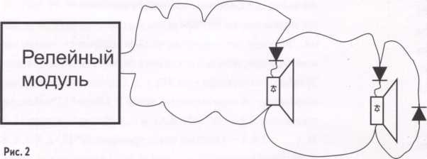
What happened? Each siren has the same diode as at the end of the line - our relay unit will not notice if the loop breaks somewhere in the middle. The result is that the manufacturers of such units (with such control technology) recommend installing an additional "direct polarity" diode for each siren. At the same time, such a diode will protect the siren from damage by the test current if the siren does not have built-in protection (alas, the race for cheapness is characteristic not only for the hero of Pushkin's fairy tale and our prospective designer, but also for siren manufacturers). Well, okay, let one more diode, it's inexpensive, especially since respected manufacturers for modest price immediately offer a ready-made block with a pair of diodes and terminals (or protruding wires) - for ease of installation. If you are building a firefighter protection system, the solution is quite good. The integrity of the communication line is undoubtedly monitored, the norms are observed. The only trouble is that additional devices and a pair of connections (or even twists) appeared between the communication line and each siren, which, of course, does not add to the reliability of the system.
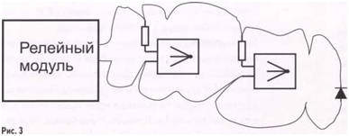
In conclusion, consider another example of transcendental greed (and at the same time amazing technical beauty), which I recently encountered in design decisions. Given: there is a fire extinguishing start-up unit, issuing 3 amperes per output. A very good unit, with a pulse stabilizer, that is, it produces exactly the guaranteed current - 3 amperes, regardless of the load. It also gives out 3 amperes for a short circuit and gives 3 amperes to a 1 ohm load (it turns out only 3 volts at the load - who remembers Ohm's law). The designer's desire was to run from this block about 100 modules of the "Buran" type, each requiring 100 mA. In principle, to connect several pyro-cartridges (fuses in Buran, strictly speaking, are not pyro-cartridges, but for the sake of simplicity I will call them that) in parallel to the output of one starting block is a perfectly acceptable solution according to existing standards. Yes, in this case it is impossible to control the connection circuits of each squib and the squibs themselves - only the notorious integrity of the communication line, but according to the norms, this is allowed. I will note, by the way, that in no car is the communication line with the airbags ever monitored - it is precisely the integrity of the airbag squibs themselves that is controlled, and each individually - but after all, it is about us, loved ones, depicting Schumacher on a slippery road, and not about any then there is an unlikely fire in the building, which we, perhaps, will never see after design. (fig. 3)
So, several squibs in parallel, the resistors are connected to them in series, so that in the event of a short circuit in the squib it does not short-circuit the entire line and interfere with the operation of the remaining squibs (usually, when the squibs are triggered, they go into a "break", but there are different cases. Although more often a short circuit is formed simply by itself, over time, due to metal corrosion and chemical processes in the filler of the igniter). The idea is simple: even if the source current after switching on is distributed unevenly, then those squibs, where the current more than the average hit, will be the first to burn out "to a break", after which the current will be redistributed over the remaining ones and the next one will work - and all this within a few milliseconds after the output is switched on. An essential condition is that the output current of the control module must certainly be sufficient for all the squibs with a margin. It should not happen that the current due to different drops on the wires and contacts at the first moment after switching on will be equally distributed "to all a little bit", so that there will not be enough for everyone to operate. Usually, manufacturers recommend a 1.5-fold stock for such an inclusion. In the case of "Burans" with a starting current of 100 mA, this means that a module with an output current of 3 A can be connected to 20 "Burans".
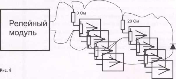
So let's get back to healthy greed. I would like to set fire to 100 "Burans" with one module (in fact, "only" 75). The current will not be enough right away - for 75 "Burans" 7.5 amperes are needed, we have only 3 A, and a small margin must be provided. You can, of course, put another couple simple relays and switch in turn 3 groups of 30 squibs, but greed does not even allow this. However, there is a solution, and a very beautiful one (do not try to repeat it in real life, the described trick is available only to trained stuntmen in helmets and with certificates from a neuropsychiatrist). So. We put different resistors in series with the squibs. We will ensure a deliberately uneven current distribution. We will connect the first group of 15 "Burans" directly. The second group (also 15 pieces) - through 20 Ohm resistors (the resistance of the squib itself is also 20 Ohm - therefore the total resistance of these branches will be twice as much). Another one - through 60 ohms, i.e. the resistance of these branches will be four times greater. And so on, there will be 6 groups of "Burans" in total, the total resistance in the branch of the first group is 20 ohms, the second - 40, then - 80.160 and finally 320 ohms. A typical binary ladder. The conductivity of the first group is even less than the sum of the conductivities of the other groups. Therefore, at the first moment after switching on, more than half of the total current (i.e., more than 1.5 amperes) will flow into this group. Accordingly, this current is enough to trigger the first group of squibs. When they are triggered, they will be "in the open" (if everything happens as expected) and the output current of the starting module will be redistributed again, so that the next group of 15 squibs will receive more than half of this current. Now they will work, and so on. A small nuisance is that the last group, in order to work, needs a voltage of 32 V, so we had to design the module's power supply from 3 power supplies of 12 volts each - a total of 36 volts. (fig. 4)
In theory, it should work. In practice, it is enough for one squib to fire "shortly" or at least simply not to fire, and most likely not a single squib in the following groups will fire. I'm not even talking about the reliability of the integrity control of such a complex structure. And, of course, this, in principle, does not work with every starting module, but only with one that provides (limits) a fixed current. If there is a conventional relay in the module, and the module tries to output all 36 volts to the output immediately, then the current in the squibs of the last group will immediately turn out to be 100 mA, in the penultimate one - 200 mA at once, etc., so the total current will exceed 40 amperes, of course, the protection of the power supply will work earlier than the squibs, and not a single Buran will start at all.
What do I want to say with all this? Greed is limitless. I do not advise anyone to never connect more than one load to one output. Parallel connection for several consumers, this is already greed, leading to a decrease in reliability, even if this is done within reasonable limits (I repeat the way to start 75 pyro-cartridges from one outlet - I gave only as an illustration of the application of Ohm's law, as an exercise for the mind). When control modules cost more than potential fire damage, this was understandable. But now, when electronics is getting cheaper every year, according to Moore's law, the right decision is to either use modules with big amount outputs (and connect one consumer to each output), or use miniature modules directly near each consumer. The second option will slightly increase the cost of the entire system (the cable structure is the same), but it can significantly improve the quality of control of the integrity of all lines, all connections and the performance of all devices (as far as it is possible to check the performance of the squib without igniting it). However, about specific decisions this class is inappropriate to speak in a generally useful informational article - it would already be direct advertising, so read about specific products in my other articles.
Two SITOP power supplies of the same type can be connected in parallel via diodes (V1, V2 in the figure) to achieve redundancy. 100% redundancy with two SITOP power supplies only exists when the total load current does not exceed the load current that one SITOP power supply can supply and the input side power supply is also redundantly configured. That is, in the event of a short circuit in the primary network of the power supply, there should be no common fuses that disconnect both sources from the power supply system.
Parallel connection with isolation diodes for redundancy is allowed with all SITOP sources. Diodes V1 and V2 are used for separation. They must have a reverse voltage of at least 40 V and must provide a rated current corresponding to the maximum output current of the installed SITOP power.
Management
The diodes must match the maximum dynamic current. This can be a dynamic short-circuit current during start-up or operation (a large value should be assumed).
To dissipate significant current x conducting-state voltage drops, diodes must be equipped with appropriately sized heatsinks.
It is reasonable to leave an additional safety margin because the input capacitor in the SITOP power supply gives an additional current peak in the event of a short circuit. However, this additional current flows for a few milliseconds and therefore in the time range (< 8.3 мс, допустимый кратковременный ток диодов) в течение которого диоды могут подвергаться многократному превышению номинального тока.
Example 1
Two single-phase SITOP power supplies with a rated output current of 10 A are connected in parallel (product order number 6ES7307-1KA00-0AA0). The dynamic current during a start-up short-circuit is approximately 22 A for 150 ms.
For safety, the diodes must have a rated current of 30 A; The heatsink must be capable of a possible continuous current (see data sheet): current limiting 13 A per diode or preferably, for safety reasons, at least 15 A per diode.
Example 2
Two DC / DC converters with a rated output current of 20 A (order number 6EP1536-1SL01) are connected in parallel. Dynamic short-circuit current of operation approx. 38 A for 500 ms.
For safety, the diodes must have a rated current of 50 A; The heatsink must be able to supply the continuous current possible (see data sheet): current limiting 23 A per diode or preferably, for safety reasons, at least 30 A per diode.
Diode type
For example, suitable type for SITOP power 20
ISOTOP module BYV 54V-50 (reverse voltage 50V).
Manufacturer
SGS Thomson
Provider
e.g. Spoerle
Advantage:
Each module contains two diodes isolated from each other and from the substrate, with a rated current of DC I F AV - 50 A each and I F RMS - 100 A. With a load current of 50 A at a voltage drop of approximately 0.8 V.
Note: BYV 54V-200 ISOTOP modules (reverse voltage 200V) are usually available from distributors.
It is generally accepted that of all the technical means of the OPS, power supplies (IP) are the simplest product. In most of the descriptions and characteristics for IP, manufacturers indicate a set of standard parameters without specifying the ways of their implementation. But since the truth is always hidden in the nuances, without understanding the meaning and methods of implementing the given indicators, it is impossible to assess the quality and capabilities of products. The easiest way is to evaluate each parameter of the IP according to its purpose and technical implementation methods.
Overload and short circuit protection. ( Note: Hereinafter, the authors do not classify all types of protection on fuse-links and self-restoring fuses as protection, considering them decorative elements of the power supply circuit.) One of the most complex indicators. Overload protection is protection against the load current exceeding a safe value, calculated for long-term operation, short-circuit protection - against critical currents that can instantly disable the source. As a rule, short circuit protection is "fast" and is set at a sufficiently high current (to exclude operation at the moment of connecting a capacitive load), overload protection is "slow" and is set at a current corresponding to the maximum permissible long-term current.
Let's say the short circuit current of a 3-amp supply is set to 8 A and there is no overload protection. If the consumer unintentionally set the current to 4 A, then it is obvious that the source will work for some time, but not for very long. Sometimes, in starting sources, the operating current in the presence of batteries is set to be higher than when operating without batteries. In this case, work will be carried out until the batteries are discharged.
It should be borne in mind that closure to closure is different, as well as overload overload. For power supplies, especially impulse ones, the most dangerous is the so-called sparking circuit, against which conventional protection is powerless in most cases. As a rule, if they try to solve the problem, then it is solved by blocking the power supply again for a while after detecting a short circuit. If you are interested in a similar parameter, it makes sense to check with the developers how it is implemented, or check on personal experience, creating frequent output short circuits.
It is especially useful to check the operation of the source for a capacitive load, since devices used as a load, as a rule, contain storage capacities. The more such devices, the greater the total load capacity. At the moment the voltage is applied from the power supply, the uncharged capacitance is perceived by it as a short circuit. The duration of this short circuit is the longer, the greater the load capacitance and the higher the resistance of the connecting wires (with an increase in the resistance of the connecting wires, the amplitude of the short circuit current decreases with a simultaneous increase in the duration). Thus, a power supply with a nominal output current of, say, 3 A may not turn on a load with an average current consumption of 100 mA, since at the moment of turning on it will constantly operate short-circuit protection.
It is quite easy to check this parameter: connect an electrolytic capacitor with a capacity of 2000 μF to the output of the source (without a battery) according to the polarity and the operating voltage is greater than the output voltage of the power supply unit, connect the source to the network. If protection works in it, you can safely hand it over to scrap metal.
Note: Let us explain why the capacitive load at the moment of switching on is perceived as a short circuit. It is known that the capacitance charge current is described by the expression: Ic = C (Uc / t), where C is the load capacitance in Farads, (Uc / t) is the rate of voltage change across the capacitance (V / s). Let a 24 V source be connected to a capacitive load of 1000 μF and a source turn-on time of 1 ms. Suppose that the internal resistance of the source and the resistance of the connecting wires to the load are equal to 0. Then the peak current of the source per charge of the load capacitance:
Ic = 1000-6 * (24/10 -3) = 24 A.
The concept of protection has another important and especially significant aspect: the ability to power a device that has several outputs or several devices, each of which has outputs. Imagine the circuit shown in Figure 1.
Rice. 1
Suppose that a short circuit has occurred in a device protected at the output by a fusible link or a self-resetting fuse. If the protection in the power supply trips before the fuse, all (all) device (s) will be de-energized and, accordingly, the existing alarm conditions will be reset. Further, the source will try to turn on, and the process, accordingly, will be repeated. As a result, the entire system will be inoperative.
The significance of this indicator is perhaps the most significant of all. We recommend that you check it after installing the system by short-circuiting any output of the device powered from it. Thus, one more parameter is secretly added to the protection against short-circuit and overload - the ability of the source to disable the safety elements of the outputs of the devices it feeds without de-energizing these devices and its own damage (critical overload holding time). If there is such a function in the sources, then it is realized only if there is a battery, otherwise the power of the source itself may not be enough to disable the safety elements.
Sources work in parallel
An essential parameter. It assumes that the sources provide for current (power) limitation, i.e. as the output current increases, the output voltage decreases so that the current does not exceed a safe value. Imagine that this function does not exist and two sources were connected in parallel, one with a voltage of 13 V, the other - 13.6 V, and the resistance of the wires between them is 0.1 Ohm. Then a current of 60 A will flow from one source to another, which will lead to the failure of one source or the operation of overload protection in it.
Redundant power supplies mean sources that operate both from the mains and from batteries in the absence of a mains, as well as having the ability to additionally recharge the mains output with battery current (in the latter case, they are also called starting power supplies). An important feature of such power supplies is the switching circuit from the mains source to the battery and vice versa, as well as additional feeding of the mains output with battery current. There are two main methods: switching to battery, current limiting circuit. Let's consider the first option. The most disgusting thing that can be is a circuit with switching to the battery and vice versa by means of a relay (Fig. 2a).
Suppose that at some point in time there is an overcurrent of the network source and the relay switches to the battery. Not only that, at the moment of switching the relay contacts, the load is generally de-energized, after switching them, the current of the network source stops, the protection turns off, and the relay contacts return back. Then the process is repeated. The diode switching circuit is more common (Fig. 2b).
Rice. 2
Its undoubted advantage is the constant power supply of the load, but it has enough disadvantages. If the mains source and the battery have different voltages, then switching from the source to the battery and vice versa, as in the previous case, will lead to voltage surges between the level of the mains source and the battery, especially noticeable in warning systems when protection is triggered for peak load currents. This is usually heard in loudspeakers as characteristic clicks. The output diodes have to dissipate significant power, which aggravates the cooling problem (at a current of 10 A, the losses are about 10 W), in addition, the drop of an additional volt across the through diode reduces the battery life.
There are also hybrid versions of both methods, in which the relay contacts are shunted by diodes (diodes work on switching, after switching relay contacts). An unavoidable problem of this method is the voltage surges noted above.
And, of course, for starting power supplies, you need to keep in mind that the overload protection current when operating from the mains and batteries must be different (otherwise the very concept of a starting block loses its meaning). In any case, a feature of all switching circuits is the underutilization of the current from the mains source when switching to a battery and, accordingly, a shorter operating time during overloads.
An alternative, but more expensive, is the current limited source circuit. Its meaning is that with an increase in the load current more than the permissible one, the output voltage of the source begins to decrease and with a further increase in the current it is compared with the voltage on the battery. In this case, the load current is distributed between the battery and the source in proportion to the slope of the voltage decrease (Fig. 3). Note: This is the same method that makes the sources work in parallel.
Rice. 3
Let's consider the operation of the circuit in stages. Let's assume that the battery is not fully charged and the voltage of the mains supply and the battery are different. With an increase in the load current and its reaching the current of the beginning of the limitation, the output voltage of the MT begins to decrease. Let the output current be set at the level of point "B", then the output voltage will correspond to the voltage on the battery, and the load current will be distributed between the current of the mains source and the battery.
As the batteries are discharged, the voltage of the source and the battery will decrease with the redistribution of currents between them. Obviously, at the entire stage of reduction, the current of the network source should not exceed the values that are safe for it, and the power supply circuit must recognize the fact of operation from the battery to set the overload protection current at a higher level.
The circuit of the starting block based on current limitation is devoid of the disadvantages of switching circuits and, which is important, allows the operation of several power supplies in parallel.
Battery charging method
Traditionally, there are two main charging methods: buffer and accelerated. Each of them has its own advantages and disadvantages. It is unambiguous that the accelerated method provides more fast charging, its technology consists in the fact that the battery is charged with a constant current (about 0.1 C) to a voltage of about 14.2 V, then the current decreases and the voltage is maintained at 13.6 V. The disadvantages of the method include the complexity of the circuit implementation, and also the leveling of the main advantage (accelerated charge) when installing a battery of a larger capacity (when installing a battery of a smaller rated capacity, the charge current will exceed the allowable one). In simple and most common systems, the principle of buffer charging is used, when the battery is connected to the power supply output voltage source through a current-limiting circuit (linear or impulse, including current limiters) (Fig.4a).
Rice. 4
During the charging process, as the voltage on the battery rises, the current decreases and the charging process increases over time (Fig. 4b). As a rule, if in technical parameters SP indicates the "maximum" charge current, we are talking about the buffer charge, and the indicated current corresponds to the voltage of the full discharge. Obviously, such information does not allow you to independently calculate the time to fully charge the battery.
The function is far from superfluous, especially in starting power supplies, where the requirements for battery health are higher than in simple ones. uninterrupted sources nutrition. Unfortunately, there is no "legalized" metrological method that provides an accelerated check of capacity, because this method involves multiple cycles of full charge and discharge of the battery with a calibrated current. In all schemes where capacity control is implemented, the principle of measuring the internal resistance of the battery and comparing the results obtained either with the initial values or with a certain limit level, after which further operation of the battery is impossible, is used. Those. capacity is measured very conventionally. Schematic diagram control is shown in Figure 5.
Rice. 5
Key K periodically connects the test resistance Rtest to ground. A divider is formed between the internal resistance of the battery Rvn and Rtest, which leads to a decrease in the monitored voltage E. The value of Rvn is determined by the degree of reduction of this voltage. Based on the analysis of the resistance, a decision is made to reduce the capacitance. Fundamentally, the method is identical to the method of accelerated quality control of car batteries.
In fact, this is the variable component of the output DC voltage. In linear sources, it is due to insufficient filtering of the input voltage of the network, in pulsed ones, by surges on the switching of power key transistors. Depends on the load current, while in linear sources with an increase in the load current, it increases, and in pulsed ones, as a rule, it decreases. Traditionally it is measured in peak values (Fig. 6) or in double peak values. For pulsed sources, a ripple amplitude of 150 mV or a ripple peak-to-peak value of 300 mV is considered acceptable.
Rice. 6
The presence of several independent outputs. The parameter is not explicitly included in the regulatory documents. Sometimes it is in demand for redundant circuits when powering several devices from one power supply. However, you should be more careful about the validity of the reservation on a case-by-case basis.
In order: Damage to the power supply circuits can be of the nature of an open or short circuit. To prevent breakage, it is enough to parallel the power wires from one output, and the problem will be solved.
Now about the closure
Situation 1. Consider the circuit shown in Figure 7. Suppose that one of the load outputs has a short circuit (the most common case). In this case, if the source cannot ensure the operation of the protection element at the load output, it will cut off the voltage at all of its independent outputs, and this will happen for all sources if several power supplies are used in the power supply system for one load.
Situation 2. The product uses a circuit for combining the main and backup power lines into one on two diodes (as shown in Figure 7), and the short circuit occurs in one of the lines to the product.
In this case, due to the voltage drop across the changed resistance of the wires of the "ground" line, a voltage surge occurs, which is applied to the "-" of the power wire. In the product, this impulse is perceived as interference, and, moreover, very serious, the amplitude of which is proportional to the resistance of the wires, and the duration - to the speed of operation of the protection against short-circuit. Further, with the frequency of attempts to turn on the short-circuited output of the MT, this interference will be repeated. The equivalent power circuit after closing is shown in Figure 8.
Situation 3. The product uses a scheme for combining the main and backup power lines into one on four diodes (as shown in Figure 9), and the short circuit occurs in one of the lines to the product. In this case, a noise pulse is not formed on the equipment, however, due to the loss of voltage across a pair of diodes (which is almost 2 V), the operating time from the battery is significantly reduced. Those. if you have a 12-volt product with a minimum supply voltage of 10 V after combining the power lines, the minimum voltage at the output of the PS when operating from a battery, when the product is still working, will not be 10.5 V, as expected, but all 12 V. e. the operating time from the battery is reduced by almost 40%, and this must be taken into account when choosing the capacity of the storage batteries. The situation with one diode, of course, is easier, but the loss of volt is still noticeable (a decrease in operating time by about 25%), especially for products with a supply voltage of 12 V. There are other schemes for combining lines (on relays, field-effect transistors), but, in - firstly, they are much more expensive to implement, and secondly, the designer, in any case, must know the minimum supply voltage of the products after this combination, so as not to be mistaken with the choice of the battery capacity.
Rice. 7
Rice. eight
Rice. nine
Rice. ten
Thus, the presence of two independent power lines sometimes not only does not solve, but exacerbates the problem.
The power supply system is not limited only to the choice of power supply c a certain amount independent outputs, but requires an integrated approach, taking into account the peculiarities of the operation of the connected equipment.
Efficiency. Efficiency is fundamentally different for pulsed and linear sources, for pulsed ones, of course, it is higher. In the group of pulsed sources, the difference in efficiency by 1-2% is practically insignificant, the thermal mode of a power supply with a lower efficiency is worse, but if the manufacturer guarantees its operation, you should not pay serious attention to this parameter.
Power factor corrector (PFC). A device that increases the power factor, i.e. reduction of the share of the reactive component in the power consumption. From the point of view of the power grid, so to speak, the load in the form of a power supply equipped with a PFC appears to be practically resistive. The power corrector is considered by many to be a device that saves electricity, however, when applied to a power supply, it performs more important functions:
- increases the range of supply voltages (as a rule, power supplies equipped with KKM have a range of input voltages of the supply network from 90 to 250 V);
- facilitates the operation of the power section of the converter and, accordingly, increases its reliability;
- reduces the level of interference radiated to the mains.
Controlled parameters. This is understood as a set of parameters automatically controlled and measured by the MT circuit. The control and display of these parameters is optional, but it is essential for the commissioning and operation of complex systems. The structure of the monitored and displayed parameters of the IP may include:
- input voltage;
- output voltage;
- output current;
- presence of an output overload;
- the presence of a short circuit;
- battery voltage;
- specific capacity of batteries;
- battery charging current;
- operability of the charger;
- and etc.
According to these characteristics, it is possible to assess the state of the power supply, the operability of the power supply and reserve batteries, the presence of breaks and short circuits in the load connection circuits, the serviceability and quality of operation of the equipment connected to the power supply. For example, an increase or decrease in the output current may indicate malfunctions of circuits or connected equipment; monitoring the battery capacity will allow it to be replaced in a timely manner. Parameters can be displayed on the IP indicators (in the full version of the liquid crystal), adjustment panels, general system panels.
In conclusion, I would like to wish everyone involved with the use of IP to be attentive to this type of product. There is no point in complex systems and expensive equipment if it turns out to be de-energized at the right time.
Start a discussion of this article in the Forum