Content... Non-linear elements. Saturation of magnetic materials. Ferroelectrics, varistors and posistors. Non-linear resistors. Semiconductor diode and its I - V characteristic. The concept of the device of bipolar transistors and thyristors. Linear voltage regulator. The principle of operation of a field-effect transistor and an insulated gate bipolar transistor (IGBT).
The values of the elements R, C, L were introduced as coefficients between current and voltage (R), charge and voltage (C), and magnetic flux and current (L). Further, from these relations, the generalized Ohm's law was formulated.
When considering the simplest problems, it was assumed that these values do not depend on the electromagnetic energy flowing through these elements. And with great pleasure we manipulated the so-called linear elements and even selected the corresponding “linear” components.
However, linear components do not exist in nature!
They can have approximately linear parameters only in a certain range of currents and voltages. Any substance, getting into the action of electromagnetic fields, one way or another, changes its structure and, accordingly, its physical characteristics, namely resistivity, dielectric and magnetic permeability, and even geometric shape. Therefore, the parameters of the components made of these materials also change, since R = rl / s; C "es / l; L "ms / l. If these changes are not significant, then we are talking about the linearity of the elements and the corresponding components. Otherwise, it is necessary to take into account these changes and then we should talk about nonlinear elements and components.
UGO of nonlinear elements in equivalent circuits are as follows:
nonlinear resistor
inductor with magnetic core
nonlinear capacitor - varicap
Non-linear elements are widely used in electrical circuits to change the shape of a signal, in other words, to excite or absorb certain harmonics that make up the signal.
From a mathematical point of view, in this case, the coefficients composed of R, C, L depend on unknown parameters (current and voltage), and the energy equations, compiled according to the Kirchhoff rules, become nonlinear with all the ensuing consequences for calculations.
The most common methods for solving them are:
- approximation when the known nonlinear dependence of the element value on current or voltage is approximated by segments of linear functions and solutions of linear equations are obtained for each of them;
- graphical method when the equations solve graphically using
known nonlinear graphical dependencies of an element on current or voltage;
- machine method, when the nonlinear dependence of the element value on current or voltage is approximated by a model mathematical function and integro-differential nonlinear equations are solved by numerical methods.
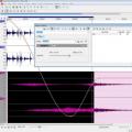
nonlinear inductance in electrical engineering use web-ampere characteristics, which are analogous to the Hysteresis curves for ferromagnetic materials that physicists like to apply. If on the Weber-ampere characteristic L = dY / dI, then on the HV curves m = dB / dH, but Y = NBS, and H »I / r. Sometimes they use volt-second characteristic, since Y = òUdt.

When approximating, this characteristic is usually divided into parts: before saturation, it is a straight line with a slope m =dB /dH, and after saturation at Vm this is a straight line with m = 1... Residual magnetization values Vr and coercive force NS determine the area occupied by the hysteresis loop, i.e., active losses due to magnetization reversal. Therefore, in most cases, they can be taken into account by introducing a resistive element into the circuit and excluded from the approximation of the Weber-ampere characteristic.
The mode of operation of inductors with linear characteristics is selected within the limits of large values of m or L. In this area, such magnetic devices as inductors for storing magnetic energy, transformers for transmitting power through the magnetic coupling of the coils, and electric motors operate. At the same time, the effect of nonlinearity of magnetic materials is widely used to create magnetic amplifiers, ferroresonant stabilizers, and even magnetic key elements in which magnetic materials with the so-called rectangular magnetic characteristic are used, where m can reach values of 50 or more. Currently, mainly 3 types of magnetic materials are used in inductors: electrical steel, amorphous iron (metaglass) and ferrites with very varied hysteresis curves.
Historically, non-linear inductors were the first to be created due to the availability and low cost of magnetic materials, as well as their ease of manufacture. They differ, first of all, in their reliability, but they have large weight and size characteristics, and in this regard, high inertia. Loss for magnetization reversal and active loss for heating windings are also a serious problem, especially in power electrical engineering. Therefore, at present, the use of non-linear inductors is limited.
To represent dependency nonlinear capacity use pendant-volt characteristics, since C = dQ / dU.

They are similar to ferromagnetic Weber-ampere characteristics, only here there is the dielectric constant e = dD / dE, where D is electrical induction or electrical displacement.
The most interesting dielectric for creating nonlinear capacitors are ferroelectrics, such as Rochelle salt (potassium-sodium tartrate), barium titanate, bismuth titanate, etc. Due to the domain structure of electric dipoles, they have a high dielectric constant at low voltages with e »1000, which decreases with increasing voltage, similar to the magnetic permeability of ferromagnets ... Therefore, in foreign literature, they received the name ferroelectrics... These materials are widely used to create linear capacitive elements such as ceramic capacitors with a high specific density of stored electrical energy, where they operate in the unsaturated region of the coulomb-voltage characteristic. Non-linearity is used to create variable capacitors, varicond that have a narrow application.
In an alternating field in ferroelectrics, there is a change in the direction of the electric moment of the dipoles, which are linked into large domains placed in crystal structures. This leads to a change in the geometric dimensions of the crystal, the so-called effect electrostriction... Magnetic materials have a similar effect magnetostriction but it is difficult to use due to the external winding. In some groups of ferroelectric crystals, effects similar to electrostriction are observed. it direct piezoelectric effect - the appearance of an electric field (polarization) in a crystal upon mechanical deformation, and back- mechanical deformation when an electric field appears. These crystalline materials are called piezoelectric, and they have found tremendous uses. The direct effect is used to obtain high voltages, in primary transducers of mechanical forces (for example, microphones, pickups in mechanical sound recording systems), etc. hard disk), etc. Both effects are used to create resonant crystal oscillators, where the dimensions of the crystals are selected in such a way that the mechanical vibrations are in resonance with the electrical ones. With a very high quality factor of such a system, stability and accuracy of tuning the generator frequency are ensured. Two such crystals, having sound communication, can transmit electrical power without galvanic coupling, for which they are called piezotransformers.
The domain structure of both electric and magnetic dipoles decays at a certain temperature, called the Curie point. In this case, a phase transition occurs and the conductivity of the ferroelectric changes significantly. On this basis, act posistors, in which, with additional alloying of the material, a certain Curie point can be set. After reaching this temperature, the rate of resistance increase can reach 1 kOhm / deg.

Essentially it is nonlinear resistor which has an S-shaped or "key" current-voltage characteristic (VAC).

That is, this element can work as an electric switch controlled by a passing current or external temperature.
Posistors are widely used to protect against current overloads in analogue telephone networks, as well as to discharge magnetic energy from coils when they are turned off, soft start of motors, etc. at almost constant temperature, and the consumed electrical power is automatically maintained equal to the dissipated heat power. That is, the fan speed can be controlled by the heat output of such a heating device.
With another type of doping of a ferroelectric, it is possible to achieve the effect of a nonlinear dependence of its conductivity on voltage, i.e., this is actually nonlinear resistor called varistor... This effect is due to a change in the conductance of thin layers of matter surrounding the domains at a certain voltage. Therefore, they are characterized by current-voltage characteristic, where the function U (I) can be represented by a polynomial of the fifth degree. It is convenient to characterize non-linear resistors with static resistance Rst = U / I and differential resistance Rd = dU / dI. It is seen that on the linear section Rst ~ Rd, on the nonlinear section Rst £ Rd.

Their main application is the protection of electrical circuits from switching emissions of dangerous overvoltages. In the varistor, the energy of such a surge is converted into active energy and heats its mass. Therefore, varistors are distinguished by two main parameters - the voltage at which the I - V characteristic breaks, and the energy that the element can absorb without disrupting its performance.
Non-linear resistors of all kinds occupy a large place in modern electrical engineering. Generally speaking, any conductor is non-linear. If a current is passed through an ordinary copper wire, then at first its resistance, as you know, will change as R0 (1 + αT). This dependence will persist until the wire is melted and then the resistance will remain constant until the material evaporates. And in this state, the wire actually becomes an insulator.
The resistance of the conductor R is inversely proportional to the current density, therefore the resistance of the bare copper conductor is considered linear up to the current density 10 A / mm2 ... With the deterioration of heat removal from the conductor, this value decreases. For example, in the winding of an inductor, this value can be at the level of 2 A / mm2. Since when these values of the current density are exceeded, an increasing release of thermal energy occurs, which leads to its melting, they are considered permissible current density values and are used when choosing safe conductor cross-sections.

This principle is used by fuses, the cross-section of the conductor in which corresponds to the limiting value of the current passing through it. But if a power of more than 1010 W / g is put into the wire, then evaporation, bypassing the melting stage, will follow the adiabat and the pressure wave of the gas evaporating from the surface will create colossal substance densities inside the material. At the same time, it was possible to free gold atoms from their electron shell and carry out thermonuclear reactions.
At a certain voltage sufficient for the appearance of a sufficient number of carriers in the gas electric charges, an electric current begins to flow in the gas gap. This phenomenon is called gas discharge, and the gas-discharge gap itself can be considered as a nonlinear resistance with the next I – V characteristic.

Gas-discharge devices are very widespread in quality and indicators, welding machines and melting units, electric switches and plasma-chemical reactors, etc.
In 1873, F. Guthrie discovered the effect of nonlinear conductivity in a vacuum tube with a thermionic cathode. When the cathode was at a negative potential, its electrons created an electric current, and with the opposite polarity, they were locked at the cathode and there were practically no carriers in the lamp. For a long time this effect was not in demand, until in 1904 the needs of radio engineering led to the creation of a thermionic (vacuum) diode. And since in such a device an electric field is responsible for conductivity, the introduction of additional small potentials makes it possible to control the flow of electrons, that is, an electric current. Thus, the electric field-controlled nonlinear resistors (radio tubes), which replaced large, inertial and current-controlled nonlinear magnetic systems. The main disadvantages of radio tubes were the incandescent cathode, which required a separate power source and appropriate cooling, as well as rather large dimensions due to the vacuum flask.
Therefore, almost simultaneously with the vacuum (thermionic) diode, a solid-state diode was created based on p-n transition, which is formed at the point of contact of two semiconductors with different types of conductivity. However, the technological difficulties in the production of pure semiconductor materials have somewhat delayed the introduction of these elements in relation to radio tubes.
When two regions with different types of conductivity come into contact, the charge carriers from them mutually penetrate (diffuse) into the neighboring region, where they are not the majority carriers. In this case, uncompensated acceptors (negative charges) remain in the p-region, and uncompensated donors (positive charges) in the n-region, which form space charge region(SCR) with an electric field that prevents further diffusion of charge carriers. In the zone p-n transition equilibrium is created with the contact potential difference, which is 0.7 V for silicon widely used in semiconductor devices.

When an external electric field is connected, this equilibrium is disturbed. With forward bias (“+” in the p-type region), the SCR width decreases and the concentration of minority carriers increases exponentially. They are compensated by the main carriers coming through contacts from the external circuit, which creates direct current which increases exponentially as the forward bias voltage increases.

With a reverse bias ("-" in the p-type region), the SCR width increases and the concentration of minority carriers decreases. The main carriers do not enter this zone, but the existing reverse current is caused only by the removal of minority carriers from the SCR and does not depend on the applied voltage. The forward and reverse currents can differ by a factor of 105 - 106, forming a significant nonlinearity of the I - V characteristic. At a certain value of the reverse voltage, the charge carriers during their free movement can acquire energy sufficient to form new pairs of charges when they collide with neutrals, which in turn gain energy and participate in the creation of new pairs. The resulting avalanche current sweeps away all potential barriers on its way, turning the semiconductor into an ordinary conductor.
UGO semiconductor diode

Typical form of the I - V characteristic of a p-n junction (diode)

An approximation of an "ideal" diode is an ideal electrical switch controlled by voltage polarity. However, this does not take into account such parameters as:
1) Forward voltage drop when a direct current flows, which in many real devices is 1 -1.5 V, and this leads to active losses P = (1¸1.5) I, and, consequently, to element heating and limiting currents for a particular element. Solving thermal problems for cooling semiconductor devices, as well as their thermal stability, are one of the main problems in the design of electrical devices. The inversely proportional dependence of the forward voltage drop on temperature limits the use of devices with pn junctions in parallel connections.
2) Reverse currents, which can be neglected only if they are several orders of magnitude less than direct currents.
3) Avalanche breakdown voltage, which determines the limit of the element's performance at reverse voltage, which must be paid attention to, especially when pulsed operation with inductive elements. However, the overall die thickness limits the reverse voltages to 1 - 2 kV. A further increase in the reverse voltage is possible only with sequential assembly of elements with equalization of reverse currents.
4) Time characteristics, in particular recovery time(the time of transition from conducting to non-conducting state), which is actually the time of removal of minority carriers from the SCR and its expansion. And this parameter is determined by diffuse processes with characteristic durations of 10-5 s. When simulating impulse characteristics in diode equivalent circuits, 2 capacitive elements are used: barrier capacity, which is determined by the size of the SCR and the space charge (it is significant at reverse voltages), as well as diffuse capacity, which is determined by the concentration of the majority and minority carriers (it is significant with a forward voltage drop). The diffuse capacity determines the times of accumulation and resorption of a nonequilibrium charge in the SCR and can reach a value of several tens of nanofarads. The development of technological processes in the manufacture of diodes made it possible to significantly affect the impulse characteristics and reduce the recovery time to tens of nanoseconds in fast and ultrafast diodes.
Therefore, the mathematical model of a real semiconductor diode developed for the Spice program and its further modifications is a rather complex mathematical expression, which includes up to 30 constants set by the user to simulate a specific element.
Work to reduce the forward voltage drop has led to the creation of Schottky diodes, in which the p-n junction is replaced by a Schottky barrier formed by a metal-semiconductor pair. This made it possible to reduce the size of the SCR and approximately halve the forward voltage drop, but at the same time, the allowable reverse voltage (< 250 В) и увеличились обратные токи. При этом улучшились импульсные характеристики, что позволило применять эти диоды при частотах до 100 кГц.
Sharp decrease dynamic resistance(Rd = dU / dIt) at a reverse breakdown voltage allows the use of diodes as voltage stabilizers, like varistors. But diodes, unlike varistors, have lower dynamic resistance values. However, it should be borne in mind that in the stabilization mode in the SCR of the p-n junction, energy is released equal to P = Ul. pr × I. Therefore, Zener diodes and avalanche diodes with p-n junction reinforced in terms of heat resistance and on their basis Zener diodes.
When a direct current passes through the SCR, the charge carriers recombine with the emission of a photon, the wavelength of which is determined by the semiconductor material. By varying the composition of this material and the design of the element, it is possible to create LEDs with coherent ( laser diodes) and incoherent radiation for a very wide spectral range, from ultraviolet to infrared light.
The development of semiconductor technology has led to the creation bipolar transistor, which is three layers of semiconductor material with different types of conductivity, n-p-n or p-n-p. These layers are called collector-base-emitter. Thus, we got 2 consecutive p-n junctions, but with multidirectional conductivity. To achieve the transistor effect, it is necessary that the conductivity of the emitter is greater than the conductivity of the base, and the thickness of the base is comparable to the width of the SCR of the collector-base junction with reverse conductivity. For work n-p-n transistor according to the scheme with a common base, the positive pole of the source is connected to the collector, the negative pole is connected to the emitter, and the base-emitter junction is opened with an additional source. In this case, minority carriers - electrons - will begin to enter the thin base layer. Some of them, under the influence of the positive potential of the collector, will pass through the closed base-collector junction, causing an increase in the collector current as a reverse current through this junction. Moreover, the collector current can be several hundred times higher than the base current ( transistor effect).
Thus, a bipolar transistor can be thought of as a non-linear resistance controlled by a base current.


UGO bipolar transistors are as follows:

I - V characteristic of a bipolar transistor or the dependence of the collector current on the collector-emitter voltage UCE (IC) for a 2N2222 transistor at different base currents.

Thus, the collector current is determined by the base current, but this dependence at low base currents is significantly nonlinear. This is the so-called active mode.
At high base currents, when the full opening of the collector-base junction is achieved, the transistor goes into saturation with a minimum collector-emitter voltage drop equal to the double contact potential difference "1.2¸1.4 V (two series connected open p-n transition). We get saturated mode.

This implies 2 possibilities of using transistors - in active mode, as amplifier, and in saturated mode - like electric key.
Consider as an example using a transistor in active mode - linear voltage regulator.

In this circuit, the transistor is connected according to a common collector circuit, that is, the collector current and base current sources are connected by a common point and the control current enters the base through the resistor Rv. Since the base-emitter junction is open, we can assume that the voltage drop across it does not depend on the current and is equal to the potential barrier UBE = 0.6-0.7V. In the absence of a zener diode DZ, the output voltage is according to the voltage divider rule UOUT ~ UIN RL / RV + RL. Zener diode DZ maintains a constant voltage level based on UZ. But then UOUT = UZ - UBE is a constant value and does not depend on the input voltage and load current. With a constant load current and, accordingly, the base current, any increase in the input voltage Uin will not change the collector current, since the dynamic resistance of the collector-base junction in the active mode of the transistor is close to ¥. At the same time, a change in the load current will simply lead to a change in the base current and, accordingly, to a change in the collector current.
The operation of a bipolar transistor in saturation mode requires the presence of large control currents, commensurate in magnitude and duration with the switched currents. Therefore, it was suggested thyristor consisting of 4 consecutive p-n-p-n layers.

 When the control current is turned on, the first pn junction (base-emitter of transistor Q1) opens and electrons from the emitter begin to penetrate through second p-n junction (base-collector of transistor Q1) .. This opens the third p-n junction (base-emitter pnp transistor a Q2) and, accordingly, the second p-n junction (base-collector of transistor Q2). This ensures that the current flows into the first pn junction and the control current is no longer needed. The deep connection between all transitions ensures their saturation.

Thus, with a short pulse of the control current, we managed to transfer the system to a saturated state with a voltage drop of about 2 V. To turn off the current in this structure, it is necessary to reduce it to 0, and this is quite simple with a harmonic signal. As a result, we got powerful semiconductor switches for AC networks, controlled by short pulses at the beginning of each half-cycle.
It is also possible to change the conductivity of a semiconductor structure by applying an electric field to it, which will create additional carriers for the current. These carriers will at the same time the main and they don't need to diffuse anywhere. This circumstance offers two advantages over bipolar structures.
Firstly, the times of the conductivity change decrease, and secondly, the control is carried out by a potential signal at practically zero current, that is, the main current is practically independent of the control current. And one more advantage arose due to the homogeneity of the semiconductor structure controlled by an electric field - this is a positive temperature coefficient of resistance, which made it possible to manufacture these structures by means of microelectronics in the form of separate microcells (up to several million per sq. Cm) and, if necessary, connect them in parallel.
The transistors created on this principle are called field(in foreign literature FET or Field emission transistor). Currently, a large number of various designs of such devices have been developed. Consider a field-effect transistor with an insulated gate, in which the control electrode ( gate), separated from the semiconductor by an insulating layer, usually aluminum oxide. This design is called MOS (metal-oxide-semiconductor) or MOS (metal-oxide-semiconductor). The space of a semiconductor, where additional carriers are formed under the influence of an electric field, is called channel, the entrance and exit to which, respectively, are called source and runoff... Depending on the manufacturing technology, the channels can be induced (p-conductivity is created in the n-material or vice versa) or built-in (a space with p-conductivity is created in the n-material, or vice versa). The figure shows a typical horizontal design of an MOS transistor with an induced and a built-in p-channel.


 UGO MIS transistor
 |
Here are the transfer characteristics of the BUZ11 transistor, namely the dependence of the drain current and drain-source voltage on the value of the gate voltage. It can be seen that the opening of the transistor begins with a certain value of Uthr and rather quickly it enters saturation.

Here is the static characteristic of the BUZ11 transistor, namely the dependence of the drain current on the drain-source voltage. The marks indicate the points of transition to the saturation mode.

Resistance of field-effect transistors to current overloads, high input impedance, which can significantly reduce control losses, high speed switching, positive temperature coefficient of resistance - all this allowed field-controlled devices not only to practically replace bipolar devices, but also to create a new direction in electrical engineering - intelligent power electronics, where the control of energy flows of almost any power is carried out with clock frequencies of the order of tens of kilohertz, that is, in fact, in real time.
However, with high currents field-effect transistors are inferior to bipolar transistors in terms of direct losses. If in a bipolar transistor, under the condition of its saturation, the losses are determined by P = IKUpr, where Upr is practically independent of the current and is approximately equal to the height of the potential barrier on two open p-n junctions, then in field-effect transistors P = IС2 Rпр, where Rпр is basically the resistance of a homogeneous channel.
The solution to this problem was found in combining field control with a bipolar transistor. This insulated gate bipolar transistor is better known by its trade name IGBT (Insulation Gate Bipolar Transistor).

UGO for IGBT

As you can see, here a p + - layer was added as a substrate to the vertical structure of the field-effect transistor, and a bipolar p-n-p transistor was formed between the emitter E and the collector K. Under the influence of a positive potential on the gate G, a conducting channel appears in the p-region, which opens the J1 junction. In this case, the injection of minority carriers begins deep into the low-resistance n-layer, the J2 layer opens slightly and a current begins to flow between the collector and the emitter, supported by the carriers in the p-layer, which keep the p-n junction J1 in the open state. The voltage drop across the JGBT is determined by the voltage drop across the open pn junctions J1 and J2, just like a conventional bipolar transistor. The off times of the JGBT are determined by the resorption times of minority carriers from these junctions. That is, the device turns on as a field-effect transistor, and turns off as a bipolar one, as can be seen from the example of switching the GA100T560U_IR device.

This structure can be thought of as a combination of a field-effect transistor and a bipolar main transistor.

The temperature dependence of the voltage drop across the JGBT is determined by the negative coefficient at the junction J2 and the positive coefficient at the channel of the p-layer, as well as the n-layer. As a result, the developers managed to make the positive temperature coefficient prevail, which opened the way parallel connection of these semiconductor structures and made it possible to create devices for practically unlimited currents.
 Assembly on IGBT for switching
voltages up to 3300 V and currents
Subject: Automatic control theory
Topic: NON-LINEAR ELEMENTS
1. Classification of nonlinear elements
Nonlinear dependences z = f (x) can be classified according to various criteria:
1. By the smoothness of the characteristics: smooth - if at any point of the characteristic there is a derivative dz / dx, that is, the function is differentiable (Fig. 1a, b); piecewise linear - a characteristic in which the derivatives have a discontinuity of the first (Fig. 2a) or second kind (Fig. 2b).
Rice. 1
Fig. 2
By unambiguity: unambiguous - in which each value of the input quantity corresponds to one value of the output quantity (Fig. 3a); multivalued - in which each value of the input quantity x corresponds to several values of the output quantity z (Fig. 3b, c, d).
Rice. 3
By symmetry: evenly symmetric - symmetric about the ordinate, that is, z (x) = z (- x) (Fig. 4a); odd symmetric - symmetric with respect to the origin of coordinates, while z (x) = - z (- x) (Fig. 4b); not symmetrical (Fig. 4c).
Rice. 4
2. Non-linear circuits
Circuits are called non-linear if they contain at least one non-linear element. Non-linear elements are described nonlinear characteristics, which do not have a strict analytical expression, are determined experimentally and set in tables or graphs.
Non-linear elements can be divided into two - and multi-pole. The latter contain three (various semiconductor and electronic triodes) and more (magnetic amplifiers, multi-winding transformers, tetrodes, pentodes, etc.) poles with which they are connected to an electrical circuit. A characteristic feature of multi-pole elements is that, in the general case, their properties are determined by a family of characteristics that represent the dependence of the output characteristics on the input variables and vice versa: the input characteristics are plotted for a number of fixed values of one of the output parameters, the output characteristics for a number of fixed values of one of the input parameters.
On another basis of classification, nonlinear elements can be divided into inertial and inertial ones. Elements whose characteristics depend on the rate of change of variables are called inertial. For such elements, the static characteristics that determine the relationship between the effective values of the variables differ from the dynamic characteristics that establish the relationship between the instantaneous values of the variables. Inertialess are called elements whose characteristics do not depend on the rate of change of variables. For such elements, static and dynamic characteristics match.
The concepts of inertial and non-inertial elements are relative: an element can be considered as inertial in the permissible (upper-bounded) frequency range, beyond which it becomes inertial.
Depending on the type of characteristics, nonlinear elements with symmetric and asymmetric characteristics are distinguished. Symmetric is a characteristic that does not depend on the direction of the values that determine it, i.e. having symmetry about the origin of the coordinate system. For an asymmetric characteristic, this condition is not met, i.e. The presence of a symmetric characteristic of a nonlinear element makes it possible in a number of cases to simplify the analysis of the circuit, carrying it out within one quadrant.
By the type of characteristic, you can also divide all nonlinear elements into elements with unambiguous and ambiguous characteristics. An unambiguous characteristic is a characteristic in which each value of x corresponds to a single value of y and vice versa. In the case of an ambiguous characteristic, some values of x can correspond to two or more values of y, or vice versa. In nonlinear resistors, the ambiguity of the characteristic is usually associated with the presence of a falling section, and in nonlinear inductive and capacitive elements, with hysteresis.
Finally, all non-linear elements can be divided into controlled and unmanaged. Unlike uncontrolled non-linear controllable elements (usually three- and multipoles) contain control channels, changing the voltage, current, luminous flux, etc. in which, change their main characteristics: volt-ampere, weber-ampere or coulomb-volt.
Depending on the type of constituent non-linear elements, non-linear circuits are called.
3. Gain of nonlinear element
Consider a nonlinear element (Fig. 5). Let's apply a harmonic signal with an amplitude - A 0 to the input of a nonlinear element and determine the first harmonic of the output signal.
In this case, for the input and output signals, the following ratios can be written
(1) is the modulus of the vector; is the vector argument.Consider the characteristic of a nonlinear element -
, which is called the complex gain of the nonlinear element. This characteristic can be plotted in the complex plane as well as the complex gain of the linear part. In this case, the characteristic - depends on the frequency of the signal and does not depend on its amplitude. Characteristic - depends on the amplitude input signal and does not depend on frequency, since the nonlinear element is inertial free. For unambiguous characteristics, its values are real values, and for multivalued ones, complex ones.Consider examples of constructing complex transmission coefficients for the most characteristic nonlinear elements -
.1. Non-linear element of the "amplifier with limitation" type. The link characteristics are shown in Fig. 6. Similar characteristics are possessed by different types amplifying and executive elements of automation (electronic, magnetic, pneumatic, hydraulic, etc.) in the field of large input signals.
If the amplitude of the input action is less than a, then this is an ordinary linear non-inertia link, while the gain k is a constant value. The phase shift between input and output is zero because the characteristic of the nonlinear element is symmetrical. As the amplitude increases -
the gain decreases. Some methods for studying nonlinear systems use the characteristic of the inverse complex gain of a nonlinear element (-1 /). This characteristic is shown in Fig. 6.Since there is no phase shift between the harmonics of the input and output signals, the characteristic coincides with the real axis.
Non-linear element of the "dead band" type. The link characteristics are shown in Fig. 7. Amplifiers of various types have similar characteristics in the area of small input signals.
Rice. 7
If the amplitude of the input signal
is located within the range ± a, then the output signal is zero, otherwise the output signal is not zero, since the peaks of the input harmonics appear. There is no phase shift. At large amplitudes of the input signal, the gain is constant, that is, the nonlinearity does not significantly affect the output signal.3. Non-linear element of the "three-position relay without hysteresis" type. Link characteristics are shown in Fig. 8. This characteristic is inherent in closed-loop relay systems.
Rice. eight
4. Non-linear element of the "relay characteristic" type. Link characteristics are shown in (Fig. 9).
Rice. nine
The first harmonic will be shifted towards the lagging side. The magnitude of the phase shift depends on the amplitude of the input signal and the magnitude of ± a.
Non-linear elements can be divided into three groups: non-linear active resistance r, non-linear inductance L and nonlinear capacitances C. An example of nonlinear active resistances are vacuum and semiconductor diodes and triodes, nonlinear inductors - inductive coils and transformers with a magnetic circuit, nonlinear capacitors - capacitors with a ferroelectric dielectric.
In each of these groups, nonlinear elements, in turn, can be divided into two classes: uncontrolled and controlled nonlinear elements.
Uncontrolled nonlinear elements can always be represented as a two-port network. The current of this two-pole network depends only on the voltage applied to its terminals. Such a non-linear element is characterized by one current-voltage characteristic. An example of an uncontrolled nonlinear resistance is a vacuum or semiconductor diode.
Controlled non-linear elements are usually multipole. The current in the main circuit of such an element depends not only on the voltage applied to the main circuit, but also on other parameters (control factors). Control factors can be electrical or non-electrical. Examples of controllable nonlinear elements with an electrical control factor are multi-electrode vacuum tubes and magnetic
nye amplifiers. An example of a controlled nonlinear resistance with a non-electrical control factor is a photoresistor, the current through which depends on the magnitude of the illumination.
Uncontrolled nonlinear active resistances according to the principle of thermal inertia can be divided into two groups: inertial and inertial.
Examples of inertial resistances are incandescent lamps and thermistors. For these elements, the dependence is essentially nonlinear only between the effective or amplitude values of currents and voltages. Due to the thermal inertia during the period of the sinusoidal current, the resistance of these elements changes insignificantly. Therefore, with sufficient accuracy for practice, we can assume that the relationship between the instantaneous values of current and voltage within one period is linear.
Examples of inertialess resistances are tube and semiconductor diodes and triodes at not very high frequencies. Here, the characteristics are nonlinear for both effective and instantaneous values of currents and voltages.
It should be noted that all real elements of electrical circuits have some nonlinearity. Therefore, the division of electrical circuits into linear and nonlinear is conditional. A circuit element can be considered linear or non-linear, depending on the degree of non-linearity and the problem that is posed when considering this circuit.
Subject: Automatic control theory
Topic: NON-LINEAR ELEMENTS
1. Classification of nonlinear elements
Nonlinear dependences z = f (x) can be classified according to various criteria:
1. By the smoothness of the characteristics: smooth - if at any point of the characteristic there is a derivative dz / dx, that is, the function is differentiable (Fig. 1a, b); piecewise linear - a characteristic in which the derivatives have a discontinuity of the first (Fig. 2a) or second kind (Fig. 2b).
Rice. 3
By symmetry: evenly symmetric - symmetric about the ordinate, that is, z (x) = z (- x) (Fig. 4a); odd symmetric - symmetric with respect to the origin of coordinates, while z (x) = - z (- x) (Fig. 4b); not symmetrical (Fig. 4c).
 |
Rice. 4
2. Non-linear circuits
Circuits are called non-linear if they contain at least one non-linear element. Nonlinear elements are described by nonlinear characteristics that do not have a strict analytical expression, are determined experimentally and are set in tables or graphs.
Non-linear elements can be divided into two - and multi-pole. The latter contain three (various semiconductor and electronic triodes) and more (magnetic amplifiers, multi-winding transformers, tetrodes, pentodes, etc.) poles with which they are connected to an electrical circuit. A characteristic feature of multi-pole elements is that, in the general case, their properties are determined by a family of characteristics that represent the dependence of the output characteristics on the input variables and vice versa: the input characteristics are plotted for a number of fixed values of one of the output parameters, the output characteristics for a number of fixed values of one of the input parameters.
On another basis of classification, nonlinear elements can be divided into inertial and inertial ones. Elements whose characteristics depend on the rate of change of variables are called inertial. For such elements, the static characteristics that determine the relationship between the effective values of the variables differ from the dynamic characteristics that establish the relationship between the instantaneous values of the variables. Inertialess are called elements whose characteristics do not depend on the rate of change of variables. For such elements, the static and dynamic characteristics are the same.
The concepts of inertial and non-inertial elements are relative: an element can be considered as inertial in the permissible (upper-bounded) frequency range, beyond which it becomes inertial.
Depending on the type of characteristics, nonlinear elements with symmetric and asymmetric characteristics are distinguished. Symmetric is a characteristic that does not depend on the direction of the values that determine it, i.e. having symmetry about the origin of the coordinate system. For an asymmetric characteristic, this condition is not met, i.e. The presence of a symmetric characteristic of a nonlinear element makes it possible in a number of cases to simplify the analysis of the circuit, carrying it out within one quadrant.
By the type of characteristic, you can also divide all nonlinear elements into elements with unambiguous and ambiguous characteristics. An unambiguous characteristic is a characteristic in which each value of x corresponds to a single value of y and vice versa. In the case of an ambiguous characteristic, some values of x can correspond to two or more values of y, or vice versa. In nonlinear resistors, the ambiguity of the characteristic is usually associated with the presence of a falling section, and in nonlinear inductive and capacitive elements, with hysteresis.
Finally, all non-linear elements can be divided into controlled and unmanaged. Unlike uncontrolled non-linear controllable elements (usually three- and multipoles) contain control channels, changing the voltage, current, luminous flux, etc. in which, change their main characteristics: volt-ampere, weber-ampere or coulomb-volt.
Depending on the type of constituent non-linear elements, non-linear circuits are called.
3. Gain of nonlinear element
Consider a nonlinear element (Fig. 5). Let's apply to the input of the nonlinear element a harmonic signal with an amplitude - A 0 and determine the first harmonic of the output signal.
 |
 |
In this case, for the input and output signals, the following ratios can be written
 (1)
(1)
where: - vector module; ![]() is the vector argument.
is the vector argument.
Consider the characteristic of a nonlinear element, which is called the complex transfer coefficient of a nonlinear element. This characteristic can be plotted in the complex plane as well as the complex gain of the linear part. In this case, the characteristic - depends on the frequency of the signal and does not depend on its amplitude. Characteristic - depends on the amplitude of the input signal and does not depend on the frequency, since the nonlinear element is inertial free. For unambiguous characteristics, its values are real values, and for multivalued ones, complex ones.
Consider examples of constructing complex transmission factors for the most typical nonlinear elements -.
1. Non-linear element of the "amplifier with limitation" type. The link characteristics are shown in Fig. 6. Similar characteristics are possessed by various types of amplifying and executive elements of automation (electronic, magnetic, pneumatic, hydraulic, etc.) in the area of large input signals.

If the amplitude of the input action is less than a, then this is an ordinary linear non-inertial link, while the gain k is a constant value. The phase shift between input and output is zero because the characteristic of the nonlinear element is symmetrical. As the amplitude increases, the gain decreases. Some methods for studying nonlinear systems use the characteristic of the inverse complex gain of a nonlinear element (-1 /). This characteristic is shown in Fig. 6.
Since there is no phase shift between the harmonics of the input and output signals, the characteristic coincides with the real axis.
Non-linear element of the "dead band" type. The link characteristics are shown in Fig. 7. Amplifiers of various types have similar characteristics in the area of small input signals.

Rice. 7
If the amplitude of the input signal is located within the range of ± a, then the output signal is zero, otherwise the output signal is not zero, since the peaks of the input harmonics appear. There is no phase shift. At large amplitudes of the input signal, the gain is constant, that is, the nonlinearity does not significantly affect the output signal.
3. Non-linear element of the "three-position relay without hysteresis" type. Link characteristics are shown in Fig. 8. This characteristic is inherent in closed-loop relay systems.
Since the characteristic is unambiguous, there is no phase shift. If the amplitude of the input signal® ¥, then the output signal turns into a pulse train. At small and large amplitudes, the coefficient k is small.

Rice. eight
4. Non-linear element of the "relay characteristic" type. Link characteristics are shown in (Fig. 9).
5. Non-linear element of the "backlash, gap" type. The characteristics of this
nonlinear element are shown in Fig. ten.
Models of nonlinear elements. Models of nonlinear elements can be realized by including an operational amplifier (at the input or at feedback) nonlinear two-terminal networks. Depending on the characteristics of the two-terminal network and the method of its connection, any non-linear dependence can be realized (Fig. 11a, b, c).
 |
Rice. eleven
Models of nonlinear links are widely used in computer simulation of automatic control systems.
Literature
1. Atabekov G.I., Timofeev A.B., Kupalyan S.D., Khukhrikov S.S. Theoretical Foundations of Electrical Engineering (TOE). Non-linear electrical circuits. Electromagnetic field. 5th ed. Publishing house: LAN, 2005. - 432p.
2. Besekersky V.A., Popov E.P. "Theory of automatic control systems". Profession, 2003 - 752s.
3. Gavrilov Nonlinear circuits in circuit simulation programs. Publishing house: SOLON-PRESS, 2002. - 368p.
4. Dorf R., Bishop R. Automation. Modern systems management. 2002 - 832s.
5. Collection of problems on the theory of automatic regulation and control / Edited by V. A. Besekersky. - M .: Science, 1978.
Those elements of the electric circuit for which the dependence of the current on the voltage I (U) or the voltage on the current U (I), as well as the resistance R, are constant, are called linear elements of the electric circuit. Accordingly, a circuit consisting of such elements is called a linear electrical circuit.
Linear elements are characterized by a linear symmetric current-voltage characteristic (CVC), which looks like a straight line passing through the origin at a certain angle to the coordinate axes. This indicates that it is strictly fulfilled for linear elements and for linear electrical circuits.
In addition, we can talk not only about elements with purely active resistances R, but also about linear inductances L and capacitances C, where the dependence of the magnetic flux on the current - Ф (I) and the dependence of the capacitor charge on the voltage between its plates - will be constant - q (U).
A prime example of a linear element is. The current through such a resistor in a certain operating voltage range linearly depends on the value of the resistance and on the voltage applied to the resistor.

Non-linear elements
If, for an element of an electric circuit, the dependence of current on voltage or voltage on current, as well as resistance R, are not constant, that is, they change depending on the current or on the applied voltage, then such elements are called nonlinear, and, accordingly, an electric circuit containing at least one nonlinear element , it turns out.
The current-voltage characteristic of a nonlinear element is no longer a straight line on the graph, it is non-straight and often asymmetrical, like a semiconductor diode. Ohm's law is not fulfilled for nonlinear elements of an electrical circuit.
In this context, we can talk not only about an incandescent lamp or a semiconductor device, but also about nonlinear inductances and capacitors, in which the magnetic flux Ф and charge q are nonlinearly related to the coil current or to the voltage between the capacitor plates. Therefore, for them, weber-ampere characteristics and coulomb-volt characteristics will be nonlinear, they are set by tables, graphs or analytical functions.

An example of a non-linear element is an incandescent lamp. With an increase in the current through the filament of the lamp, its temperature increases and the resistance increases, which means it is not constant, and therefore this element of the electrical circuit is nonlinear.

For nonlinear elements, a certain static resistance is characteristic at each point of their I - V characteristic, that is, each ratio of voltage to current, at each point on the graph, is assigned definite meaning resistance. It can be calculated as the tangent of the angle alpha of the slope of the graph to the horizontal axis I, as if this point lay on a line graph.

Nonlinear elements also have a so-called differential resistance, which is expressed as the ratio of an infinitesimal voltage increment to the corresponding change in current. This resistance can be calculated as the tangent of the angle between the tangent to the I - V characteristic at a given point and the horizontal axis.

This approach makes possible the simplest analysis and calculation of simple nonlinear circuits.

The figure above shows a typical I-V characteristic. It is located in the first and third quadrants of the coordinate plane, this tells us that with a positive or negative voltage applied to the p-n-junction of the diode (in one direction or another), there will be a forward or reverse bias of the p-n-junction of the diode. With an increase in the voltage across the diode in any of the directions, the current at first slightly increases, and then sharply increases. For this reason, the diode belongs to an uncontrolled non-linear two-pole network.

This figure shows a family of typical I – V characteristics under various lighting conditions. The main mode of operation of the photodiode is the reverse bias mode, when, at a constant luminous flux Ф, the current is practically unchanged in a fairly wide range of operating voltages. Under these conditions, modulation of the light flux illuminating the photodiode will result in simultaneous modulation of the current through the photodiode. Thus, a photodiode is a controlled nonlinear two-pole device.

This is the I - V characteristic, here you can see its clear dependence on the magnitude of the control electrode current. In the first quadrant - the working section of the thyristor. In the third quadrant, the beginning of the I - V characteristic is a small current and a large applied voltage (in the locked state, the thyristor resistance is very high). In the first quadrant, the current is large, the voltage drop is small - the thyristor in this moment open.
The moment of transition from the closed - to the open state occurs when a certain current is applied to the control electrode. Switching from an open state to a closed one occurs when the current through the thyristor decreases. Thus, a thyristor is a controlled nonlinear three-pole device (like a transistor in which the collector current depends on the base current).