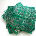
Single-ended stripline transmission line
An asymmetric strip transmission line or microstrip line (Fig. 12.3, 12.4, a) is a strip line in which the conductor (1) is separated from the general metallization (3) by a dielectric layer (2). Such a line is easily manufactured using modern technological processes, has small dimensions, low cost for mass production, and high reliability. The distribution of electric and magnetic field strength lines is shown in Fig. 12.4 , b. Despite the obvious simplicity of the design, an accurate analysis of the characteristics of a microstrip line having a non-uniform dielectric medium is quite complex. Line characteristics are calculated, as a rule, under the assumption of quasi-T-wave propagation. Strictly speaking, a mixed wave propagates in a line and has noticeable dispersion, which causes its parameters to vary with frequency. Accurate determination of frequency-dependent parameters is possible when solving a boundary value problem using numerical methods on a computer.
Rice. 12.3. Design of Single-ended Stripline Transmission Line

Rice. 12.4. Design of single-ended strip transmission line (a) and distribution of electric and voltage lines magnetic field(b).
For NPL, calculating wave resistance and other parameters is a more complex task than for SPL. The main difference is that the NPL is an open structure, and the construction of its rigorous theory turned out to be associated with solving a number of complex problems in the mathematical theory of diffraction and computational electrodynamics. At the same time, various approximate results turned out to be very useful for a number of applications. One such approach involves the use of the so-called Oliner model. This model is based on a comparison of the characteristic impedances of a real line having a relative dielectric constant of the substrate material ε r and a uniformly filled waveguide with magnetic side walls. Moreover, the filling of this waveguide has the value ε eff– effective relative dielectric constant different from ε r .Value ε eff determines the equality of phase velocities in both lines. Effective width W eff The NPL for the Oliner model is determined from the equality of the wave impedances of the original line and the model.
A number of approximate relations have been obtained to determine the wave resistance Z IN and effective relative dielectric constant ε eff in a quasi-static approximation. So, wave resistance Z IN can be calculated with low error (±1%) for 1 ε r16 and geometric dimensions in the area .
For wide conductors ()
and for narrow conductors ()
![]() , (12.8)
, (12.8)
where is the parameter ε eff is equal to:
Losses in an MSL are usually divided into losses in the dielectric of the substrate, in the metal elements of the line, and into radiation into the surrounding space due to surface and spatial types of waves. To calculate losses in the metal and dielectric of the substrate, fairly simple calculation relationships are known. Radiation losses are usually associated with the presence of various types of inhomogeneities in the PLP. So, it could be a line break, or a bend in it; hole in the center conductor; another line located nearby (in this case we talk about connected PLPs).
The attenuation coefficient due to losses in the dielectric is determined by the following formulas:
; [dB/m] (12.11)
Where ![]() , where is the frequency [GHz].
, where is the frequency [GHz].
When taking into account the finite thickness of the conductor instead of the ratio W/ D you need to substitute the value W * / D:
![]() , (12.12)
, (12.12)
![]() . (12.13)
. (12.13)
Addiction Z IN from the relationship with different meanings ε r(curve 1 corresponds ε r = 2.2; curve 2 - ε r = 4.0; curve 3 - ε r =6.0; curve 4 - ε r = 9.6) can be shown by the curves shown in Fig. 12.5. Analysis of these curves shows that the value Z IN in MPL decreases with increasing W, ε r and with decreasing substrate thickness D.
Calculations show that at the values of the MPL parameters W= 1 mm, D= 1 mm, made on the basis of polycor with ε r = 9.6, its wave impedance is approximately 50 Ohms.
A more rigorous analysis shows that it is not a pure T-wave propagating in the MPL, therefore the characteristic impedance and effective dielectric constant depend on the operating frequency. This dependence is called dispersion. In the calculated relationships presented above, when taking dispersion into account, it is necessary to replace by .

Rice. 12.5. Dependence of wave resistance on design parameters and dimensions.
Based on a generalization of numerous experimental data, the following empirical formula was obtained to take into account the frequency dependence:
![]() , (12.14)
, (12.14)
![]() , (12.15)
, (12.15)
Where f- operating frequency [dimension in GHz], dimension W And D in comparable quantities.
The accuracy of calculations using formulas (12.14) and (12.15) is no worse than 2% at and mm.
Attenuation coefficient m in metal is determined by the following approximate formulas:
![]() (12.17)
(12.17)
where , a is the conductivity of the material used for the manufacture of microstrip line conductors, and is the conductivity of copper.
 (12.18)
Where ; ![]() ;
;
;
.
;
;
;
.
In Fig. Figure 12.6 shows the dependence of the attenuation coefficient of a microstrip transmission line on frequency at parameter values r = 9,6, D = l mm, = 75 Ohm (curve 1) and = 50 Ohm (curve 2.) It can be seen that with increasing frequency the attenuation coefficient increases according to the law f. With increasing wave resistance, losses also increase, provided all other parameters are equal. Real microstrip circuits are housed in a shielding package. At the same time, the idealized idea of conducting boundaries located at an infinite distance from the strip turns out to be inaccurate in a number of cases. However, it is considered that if the shielding housing is located at a distance greater than 10 W, then the parameters of such a transmission line can be determined using the formulas presented above for lines without shielding.
In real microstrip lines, attenuation increases due to the roughness of the substrate, the finite thickness of the adhesive sublayer between the conductor and the substrate, as well as due to a number of other factors not taken into account above.

Rice. 12.6. Dependence of attenuation of a microstrip transmission line on frequency.
where is the value f cr expressed in GHz, and D - in mm.
In the continuous oscillation mode, losses in the microstrip line, as well as the intensity of heat removal from the substrate, determine the electrical strength. Approximate values of maximum average power for a line with a sapphire substrate are 80 - 100 W , and the maximum pulse power (with a signal duty cycle of more than 50) is several kilowatts.
From the above it is clear that the electrical characteristics of a microstrip line are determined by its geometric dimensions. Reducing the thickness of the substrate provides: low radiation losses, reduced probability of excitation of surface waves, increased installation density. However, other things being equal, to maintain constant wave resistance it is necessary to reduce W, which, in turn, leads to increased losses in conductors. In addition, for small values of the parameters D And W the required manufacturing tolerances to ensure satisfactory electrical performance may be difficult to achieve. A compromise solution when choosing D is an accepted series of standard values for substrate thickness for microstrip lines: D = 0.25; 0.5; 1 mm.
Let us dwell on the definition of another geometric dimension of a microstrip line - the thickness of the conductor. The current in a microstrip line conductor flows primarily along the side of the conductor facing the substrate and is concentrated in a layer whose thickness is approximately equal to the thickness of the skin layer. To ensure low losses in the conductor, it is necessary that the thickness of the conductor and the grounded plate be approximately 3 -5 times the thickness of the skin layer.
Strip (or tape) lines have become widespread due to the introduction of microwave technology printed circuits. They are used primarily in the centimeter and decimeter ranges. They are made on the basis of dielectric plates covered with metal foil of thickness
High-frequency dielectrics are used: fluoroplastic, polystyrene, polyolefins, fiberglass impregnated with fluoroplastic or polyarganic resin.

An asymmetrical line (Fig. 10.14a) is structurally the simplest, but has a significant drawback: part of the wave propagates in the air and causes unwanted connections with other elements of the circuit. Symmetrical line (Fig. 10.146) “dielectric sandwich” - almost completely shielded a. Given the width of the outer plates, there is practically no roofing felt at their edges; In this case, the strip line is equivalent to a coaxial line with very narrow slots in the outer conductor.
The attenuation coefficient of a line with a faulty dielectric is determined mainly by losses in the dielectric. This source of loss is almost completely eliminated in an overhead line (Fig. 10.14c), in which the conducting strips are located on both sides of a thin dielectric sheet and connected (to each other; the supports of this sheet are removed to an area where the field is practically absent. The wide plates of the lines are grounded and connect with each other.
WAVE TYPES
The main wave in a strip line is the TEM type wave. The dielectric layer has finite dimensions, so a surface wave is formed at its boundary in the air. However, the field of this wave is so small compared to the field in the dielectric that the difference between the structure of the water in a line and the transverse one, especially in symmetrical structures, may not be taken into account.
The occurrence of (waves of higher order) is excluded if the equivalent width of the tape and the distance between the outer plates is less than half the wavelength in the dielectric of the line: the fulfillment of these conditions at the maximum frequency ensures single-mode line in the operating range.
Equivalent width of the tape (greater than geometric due to the edge effect. The amount of equivalent expansion is calculated by the formula
The approximate formula for gives an error of no more than 2% at
MAIN PARAMETERS
The resistance of a symmetrical line is determined by the capacitance C, unit of its length. The latter is determined by the formula for flat capacitor of three plates, taking into account the additional capacity caused by the edge effect. Equivalent to a strip of unit length, the distance between it and the plates is two capacitors connected in parallel. Therefore, from where according to formula (10.9)
![]()
This formula is valid three times When obtained (the result should be increased by 4%.
The characteristic resistance of an asymmetrical line with a solid dielectric is approximately two times greater than that found by since it is determined by the capacitance between the tape and one plate: The field of an asymmetrical line is wider than that of a symmetrical one: and is determined by the approximate relation Accuracy of 2-5% is given by formulas for symmetrical and asymmetrical lines with air filling, obtained by I. S. Kovalev.

Attenuation coefficient The component is determined by the universal formula (8.43). Analysis of losses in conductors is a difficult task due to the uneven distribution of the field along their surface. To a first approximation, we will assume that the current density along the perimeter of the tape is the same, and the resistance of the plates is the same as the tape. Then the total resistance per unit line length and the attenuation coefficient in accordance with formulas (10.11) are determined as
With the usual ratios of line sizes, the losses in the plates are somewhat less, and in the tape more, than with the assumptions made.
The maximum power of a symmetrical strip line, determined by breakdown, is 1.5-2 times (less than that of a rectangular waveguide with the same transverse dimensions. When transmitting continuous signals, the permissible power is limited by heating the dielectric. A symmetrical line can transmit power by 1.5 times larger than unbalanced or coaxial lines.
APPLICATION OF STRIP LINES
Strip lines are used primarily in the range for transmitting (low (powers). Their advantage compared to hollow waveguides is ease of manufacture, (compactness and low cost. Short sections of lines can be built for more high frequencies, if the attenuation coefficient is acceptable (several decibels per meter.
The advantages of strip lines produced by the printed circuit method are especially noticeable when constructing small-sized functional units (for example, frequency filters) in microwaves. For this purpose, such lines are successfully used, starting from hundreds of megahertz.
In mini-integral circuits, microwaves are used as more technologically advanced (unsymmetrical microstrip lines. The strip width is usually To reduce the penetration of the field into the air, a dielectric with a high value is used
→ Asymmetry ohmic and capacitive
Electrical capacity. Search for breaks and brokenness
Near-end coupling loss measurement
Pulse cable measurement method
Asymmetry
No matter how scary the incomprehensible word is, you will have to delve into its logical meaning. Everyone is familiar with the concept of symmetry. This is when both sides are the same - like wheels or headlights in a car or eyes on a face, that is, when the right one is the same as the left. Accordingly, asymmetry is when it is asymmetrical: the right is larger than the left or vice versa.
Now let's get back to cables and lines. In the vast majority of cases, cables and communication wires with metal conductors use paired (symmetrical) lines, that is, all the parameters of one wire of a pair are the same as the parameters of the second wire of the same pair. These parameters are: core resistance, insulation, electrical capacitance to the screen (ground) and inductance. Accordingly, the difference in them is called asymmetry. In this case, asymmetry is distinguished:
→ according to the resistance of the cores - ohmic asymmetry
→ by capacity to ground (screen) - capacitive asymmetry
→ by insulation to ground (screen) - asymmetry in insulation
→ by inductance - loop inductance asymmetry
The loop inductance asymmetry is not measured. Insulation asymmetry in the case of a decrease in the insulation of one wire below the norm is called “ground” or damage, and in other cases it is not measured.
During planned and acceptance measurements, ohmic asymmetry is measured. And relatively recently and in connection with active use Capacitive asymmetry began to be measured in DSL modems.
Asymmetry ohmic
Ohmic asymmetry - the difference in the resistance of the two wires of a pair to direct current.
Measuring the resistance of one core in a laid cable is problematic. It is much easier to compare two at once. For this purpose, the PKP, IRK-PRO, etc. devices have a corresponding bridge circuit. The cords are connected in the same way as in loop measurement, only the shorted pair at the other end is grounded or connected to the cable shield. The appropriate measurement mode is selected, and the answer is obtained in Ohms. It remains to compare with the pair's loop and the norm of 0.5% (STS) or 1.0% (GTS).
↓ Officially ↓
As a rule, a slight asymmetry (1-2%) is obtained due to the difference in the diameters of the cores in the cable pair. Which, in turn, occurs due to the wear of the dies when drawing cores at a cable factory. Or more simply, due to insufficient control of manufacturing technology.
There is an idea that the asymmetry in the installed cable length occurs due to poor-quality twisting of the couplings and poor contact in the plinths. The resistance introduced by the contacts of the plinths and connectors in the couplings is very small and is not capable of introducing a significant difference.
The standard for this resistance is in the appendices to
OST 45.36-97→ Characteristics of connectors for conductive cable cores
OST 45.62-97 pages: → Characteristics of cable core connectors and → Characteristics of plinth connection modules
By performing incoming inspection of the cable coming from the factory, you can make sure that there is asymmetry before installing the couplings. And, as a rule, poor twisting during installation has much greater resistance and very quickly turns into a break. So the main “supplier” of abnormal asymmetry is the cable plant.
__________
P.S. 02/12/14. It is curious that in GOST R 54429-2011 Symmetrical communication cables for digital systems transfers. General technical conditions requirements for ohmic asymmetry are not so strict ↓
5.2.2 Electrical requirements
5.2.2.1 Electrical resistance of the conductor to direct current, recalculated for a length of 1000 m and a temperature of 20°C, must be:
- no more than 95 Ohms - for cables for SCS with a single-wire core;
- no more than 145 Ohm - for cables for SCS with a stranded core;
- no more than the value specified in the technical specifications for cables of specific brands for broadband access.
5.2.2.2 The ohmic asymmetry of the cores in the working pair should be no more 3%
for cables of categories 3 and 5 and no more 2%
- for cables of categories 5e, 6, 6A, 7 and 7A.
Since this document is about the resistance of one core, and not about a loop, then to recalculate the percentage of ohmic asymmetry to the resistance of the loop, the values of 3% and 2% should be divided by two. That is, it will turn out 1,5% And 1% and these numbers are comparable to the norm 0,5% from OST 45.83-96 or 1% from OST 45.36-97
Asymmetry capacitive
Capacitive asymmetry is the difference in capacitance to the ground (screen) of the two wires of a pair. For example, the capacitance of core “a” to “ground” is 36 nF, and the capacitance of core “b” is 35 nF. We subtract the larger from the smaller (so as not to throw out the resulting minus) and get the absolute capacitive asymmetry in nanofarads (nF)
A c =|C a -C b |, (nF)
Here
A c - capacitive asymmetry
C a - capacity of core “a” to the screen
C b - capacity of core "b" to the screen
Calculation: A with =36-35=1(nF)
To calculate the relative asymmetry (A co), you need to divide the resulting value by the capacity of one core and multiply the result by 100%, that is
A co = A c / C a * 100%,
Calculation: A co =1/36*100%≈2.8%
The norm is "no more than 5%"
Just like ohmic asymmetry with normal line insulation, it cannot be corrected by repairing the cable, but only by replacing it.
Problems associated with asymmetry in communication cables. Measuring communication lines. Asymmetry.
Why is asymmetry measured and what line parameters does it affect?
A telephone wire transmitting a signal surrounds itself with an electromagnetic field. The second wire of the pair, given that the current flows in it in the opposite direction, completely balances this interfering field. If a couple has a large asymmetry, then balancing does not occur. The signal on such a pair creates interference in the cable, and vice versa, any interference penetrates into this line. That is, asymmetry affects the security of the line.
For a regular phone, as a rule, there are no problems from slight asymmetry. Problems arise with modems and faxes, and in turn there are more and more of them on our lines.
In addition to transmission parameters, there is a huge impact on electrical characteristics symmetrical cables are also influenced by parameters.
PARAMETERS OF INFLUENCE
The main method of reducing such influences is to twist the cores of a copper pair. The most stringent requirements in this regard are imposed in structured cable systems (SCS) with a wide range of operating frequencies: the absence of twisting of the cores is allowed at a distance of no more than 1/2 inch from the point of connection of two cable sections.
The measure for assessing transient influences is the near-end crosstalk (NEXT) and the far-end crosstalk (FEXT). The specified parameters allow us to evaluate the suitability of pairs of symmetrical cables for high-speed data transmission. Transient attenuation NEXT and FEXT can be expressed through the logarithm of the ratio of the power of the generator P 1 feeding the influencing circuit to the interference power P 2 in the influenced circuit, i.e. as 10lg (P 1 / P 2) dB or as the difference in levels in the indicated points p 1 - p 2.
It is worth recalling that the signal or interference level at an arbitrary point X of the communication line is estimated as px = 10lg (P x / 1 mW) dB. Here P x represents the signal power at point X. Sometimes the notation dBm is used instead of dB to emphasize the fact that the signal power of 1 mW is chosen as the reference power. Below will be used short designation dB.
The NEXT value is estimated by the difference in signal levels at the output of the transmitter of one pair and the interference it creates at the input of the receiver of the other, measured at the same point, i.e. NEXT = p 10 - p 20.
The NEXT parameter is decisive in single-cable mode of operation of the communication line, when signals of opposite transmission directions are transported along pairs of one cable. It also plays a key role in cases where the echo cancellation method is used to separate signals of opposite directions transmitted over one pair. As is known, the spectra of signals from opposite transmission directions completely (for example, for HDSL) or partially (for ADSL) coincide. Previously, in the domestic technical literature, the designation A 0 was used for the NEXT parameter.
The FEXT value is estimated by the difference in signal levels at the output of the transmitter of one pair and the interference it creates at the input of the receiver of the other. However, unlike NEXT, in FEXT measurement the transmitter of the influencing pair and the receiver of the affected pair are located at opposite points on the transmission line.
FEXT is a determining parameter in a two-cable mode of operation of a communication line, when signals of opposite transmission directions are transported through pairs of different cables. It is also of key importance when FDM is used to separate signals of opposite directions transmitted over the same pair (for example, in ADSL or VDSL systems). Then the spectra of signals from opposite transmission directions do not overlap, and there is no transient influence at the near end. Previously, the FEXT parameter was usually denoted as A L .
All other things being equal, the value of FEXT is significantly greater than NEXT, since in the first case the influencing signal undergoes attenuation in the communication line, and in the second it directly affects the affected pair.
As the line length L increases, the NEXT parameter first decreases and then stabilizes: starting from a certain length, interference currents from remote sections arrive so weakened that they practically do not affect the NEXT value. The situation is different in the case of the addition of mutual influence currents at the far end - as the length of the line increases, all its sections introduce the same values of interference. Crosstalk loss decreases with increasing frequency, with NEXT decreasing with frequency at a rate of 15 dB per decade and FEXT decreasing at a rate of 20 dB per decade. The lower slope of the frequency dependence of FEXT is explained by the fact that with increasing frequency, the attenuation of transient interfering currents arriving at the near end from remote sections of the line increases.
In addition to the considered NEXT and FEXT parameters, two new ones are widely used in the practice of assessing structured cabling systems - ACR and ELFEXT, which we will discuss in more detail.
The Attenuation to Crosstalk Ratio (ACR) is equivalent to the near-end crosstalk signal-to-noise ratio NEXT, i.e., it serves as an estimate at the receiver input for the line-attenuated signal and the near-end crosstalk interference. Quantitatively, ACR is expressed as a logarithmic measure of the difference between NEXT and cable attenuation. If, for example, the ACR value is 10 dB, this means that the NEXT interference power at the receiver input will be 10 times less than the wanted signal power, i.e. the signal-to-noise ratio will be 10.
Let the communication system operate in single-cable mode, and the signal levels at the outputs of the transmitters at points A and B are the same and equal to 0 dB. If the line attenuation at frequency f is denoted by a k, then with the transition attenuation NEXT at the same frequency, the levels of the signal p c and the transient interference p p at the input of receiver A will be, respectively, equal to a k and NEXT.

Then ACR = p c - p p = NEXT - a k.
The practical meaning of the ACR parameter becomes clearer if frequency characteristics the attenuation of the symmetrical pair (a), the transient noise (NEXT) and the parameter (ACR) are presented on one graph. The frequency at which the attenuation and NEXT values are the same (in this case it is 100 MHz) determines the upper limit of the operating frequency range. At frequencies above the limit, the NEXT interference power exceeds the signal power.
The Equal Level Far End Crosstalk (ELFEXT) parameter has the same physical meaning as ACR. The only difference between them is that ACR is associated with NEXT, and ELFEXT is associated with FEXT. The ELFEXT parameter becomes critical for cases when several transmitters of the same system transmit in one direction over pairs located in the same cable.
In this case, ELFEXT = FEXT - a k.
It is worth noting that previously in the domestic technical literature the designation A z was used for the ELFEXT parameter, which was called protection from transient influence at the far end.
In addition to the ACR and FEXT parameters, two additional parameters- PS-ACR (Power Sum ACR) and PS-ELFEXT (Power Sum ELFEXT), taking into account the total influence on a given pair of all other cable pairs.
LINE ASYMMETRY
Asymmetry is both a transmission parameter, since it is determined by the parameters of the pair and affects its throughput, and an influence parameter, since it affects transitions between other pairs.
Each symmetrical line must be balanced relative to the ground in a certain way. Depending on the current - direct or alternating - two types of asymmetry are distinguished.
Direct current asymmetry is assessed by the relative value of the difference in the resistance of the cores of a symmetrical line and should not exceed 1%. The presence of a resistive unbalance of the line, equal to the difference in the resistance of its cores, measured at alternating current, can be interpreted as the inclusion of an additional low-pass filter with a longitudinal arm resistance dR. In addition to the resistive component, the longitudinal imbalance of the line in the general case also contains a capacitive component; it can arise, for example, due to accidental crossing of wires of different pairs at cable junctions. This component can be interpreted as the transverse capacitance of that additional low-pass filter mentioned above.
The degree of longitudinal asymmetry in alternating current is assessed by the magnitude of the attenuation of longitudinal asymmetry (Longitudinal Conversion Loss, LCL). The causes of longitudinal imbalance of twisted pair cores may be loose contact at the junction points of cable cores (twisting or soldering points, distribution cabinets, etc.). The problem of longitudinal imbalance cannot be considered solved, even if the longitudinal asymmetry of the pair in question is brought to normal. This fact is a necessary, but not yet sufficient condition for solving the problem of longitudinal asymmetry in a particular cable. The sufficiency condition requires mandatory checking of all pairs of beams or layers for compliance with the standards of longitudinal asymmetry. The fact is that any imbalance of even a non-working pair is a source of interference for all working pairs, which results in a decrease in their throughput.
Digital communication with a subscriber and digital modems
For most of the past century, connecting the subscriber's telephone to telephone exchange(or “local section of the communication line”, “last mile”) was carried out by copper wire (“twisted pair”, hidden in underground collectors or stretched through the air.
For a long time, the used bandwidth did not exceed 3 kHz, which was limited by analog terminal devices. However, twisted pair is inherently capable of much higher bandwidths, and can carry video or broadband data over short distances. New technologies (ISDN and ADSL) have been developed to provide higher performance within existing infrastructure.
In addition, in the 1990s. Cable TV companies have invested heavily in alternative channels to reach homes. Both twisted pair technologies and fiber optic and coaxial cables were used here. In most cases, these cable networks were carried out to provide broadcast television. However, their communication capabilities and high bandwidth can also be used to provide other forms of digital services.
The Integrated Services Digital Network (ISDN) might be considered the best-too-long-kept secret of the computer networking world. ISDN was hidden from public switched telephone network (PSTN) users for a long time, since it only provided communication between telephone exchanges, and the subscriber to the exchange was still connected via an analog channel.
ISDN was originally available in two versions:
Basic Rate ISDN - BRI, which is also known as ISDN-2. BRI is intended for the home user or small business, consisting of two “B channels” (64 Kbps) for data transmission and one covert “D channel” (16 Kbps) for control information. Two
64 Kbps channels can be used separately or connected together to form a 128 Kbps channel;
Primary Rate ISDN - PRI or ISDN-30. The PRI consists of 30 "B channels" (a minimum of six can be configured) of 64 Kbps, plus a 64 Kbps "D channel" for control data. B-channels can be combined into a single 1.92 Mbit/s channel.
In late 1998, British Telecomm (BT) made its first serious attempt to bring ISDN technology to the home user with the announcement of the BT Highway service. If a customer subscribes to one of these services, the existing telephone line is retained, but the old main jack is replaced with a Trunk module. It has four connectors, two analog and two ISDN, and can support up to three conversations simultaneously. The subscriber keeps the old analog telephone number and receives two additional ones, one for the second analog port and one for ISDN lines. The two main differences between Home and Business services are that the latter supports Multiple Subscriber Numbering (MSN), whereby different devices connected to the same ISDN line can have different phone numbers, and also provided new service data connection (ISDNConnect) or an always-on slow connection that uses an ISDN signaling channel.
At the same time, Internet-onepaTop BT, BT Internet, announced support for 128 Kbps, allowing users to use two ISDN lines as one with high bandwidth.
xDSL is the collective name for a variety of Digital Subscriber Line (DSL) technologies designed to offer telephone companies a path into the cable television business. This is not a new idea - Bell Communications Research Inc developed the first digital subscriber line back in 1987 to provide video on demand and interactive television via wired connection. At that time, the spread of such technologies was difficult due to the lack of industry-wide standards.
xDSL technologies offer incoming (download) speeds of up to 52 Mbit/s and outgoing (download) speeds from 64 Kbit/s to 2 Mbit/s (or more) and have a number of modifications:
Asymmetric line (ADSL);
Single line (SDSL);
Very high speed data transmission (HDSL).
Practice shows that ADSL lines (Asymmetric
Digital subscriber line) are most promising for domestic use.
ADSL. ADSL technology similar to ISDN - both require wired telephone lines to be clear and can only be used within a limited distance from the local telephone company. In most cases, ADSL can operate over twisted pair connections without disrupting existing telephone connections, meaning local telephone companies do not have to install special lines to provide ADSL service.
ADSL takes advantage of the fact that since voice communications do not take up all the bandwidth available on standard twisted pair cables, high-speed data transmission can be carried out at the same time. To this end, ADSL breaks the maximum wired connection bandwidth of 1 MHz into 4 kHz channels, of which one channel is used for the plain old telephone system (POTS) - voice, fax and analog modem data. The other 256 available channels are used for parallel digital communications. Communication is asymmetrical: 192 channels of 4 kHz are used to transmit incoming information and only 64 for outgoing information.
ADSL can be thought of as converting a serial line of digital data into a parallel line, thus increasing throughput. The modulation technique is known as Discrete Multitone (DMT), encoding and decoding are performed respectively, in the same way as a conventional modem.
An earlier system, called Carrierless Amplitude Phase (CAP), was capable of using the entire bandwidth above 4 kHz as a single transmission channel and had the advantage of
Rice. 3.9. Network with connection via ADSL modem: / - telephone input; 2 - analog output; 3 - digital output
The advantage is that it is similar to the Quadrature Amplitude Modulation (QAM) technique used by high-speed modems at speeds greater than 9.6 Kbps, and is also cheaper to implement. However, DMT, a more robust, sophisticated and flexible technology, proved more suitable for a universally accepted standard.
When the service began to be commercially available, the only equipment ADSL subscribers had to use was a special modem. The device has three connections - telephone input (Fig. 3.9, /); a standard RJ11 telephone jack for servicing an analog telephone (Fig. 3.9, 2) and a twisted pair Ethernet connector that connects the ADSL modem to the PC (Fig. 3.9, 3).
On the user side, the ADSL modem collects high-frequency digital data and translates it for transmission to a PC or network. On the telephone service side, a Digital Subscriber Line Access Multiplexer (DSLAM) connects an ADSL user to high-speed Internet by aggregating incoming ADSL lines into a single voice or data connection. Telephone signals are sent to the switched telephone network, and digital signals are sent to the Internet via a high-speed backbone (fiberglass, asynchronous data transmission, or digital subscriber line).
Currently, there are various designs of ADSL modems. Some connect to the PC via a USB port, others via Ethernet cable. Most devices allow
It is not possible to share the Internet connection between several PCs. An integrated modem/router supports a PC network, some include an integrated network security system (firewall) to provide various levels of protection against unauthorized access.
192 channels at 4 kHz provide a maximum bandwidth of 8 Mbps. The fact that ADSL services are limited to a limit of 2 Mbit/s is due to artificial bandwidth reduction and the fact that actual service levels depend on a number of external conditions. These include wiring length, number of sensor wires, dangling pairs, and interference. Signal attenuation increases with line length and frequency and decreases with wire diameter. A "dangling pair" is an open wire pair that is parallel to the main wire pair, for example, each unused telephone jack is a dangling pair.
If we ignore the influence of dangling pairs, ADSL performance can be presented as it looks in table. 3.11.
In 1999, based on proposals from Intel, Microsoft, Compaq and other equipment manufacturers, a specification was developed that was adopted by the International Telecommunication Union (ITU) as a universal ADSL industry standard, known as G.922.2 or G.lite. The standard assumes that users can make regular voice calls phone calls simultaneously with the transmission of digital data. Some speed restrictions are being introduced - 1.5 Mbit/s for data reception and 400 Kbit/s for transmission.
ADSL2. In July 2002, the International Telecommunication Union finalized two new asymmetric digital subscriber line standards, defined as G992.3 and G992.4 for asymmetric digital subscriber line (hereinafter known as ADSL2).
The new standard was designed to improve the speed and range of asymmetric digital subscriber lines, achieving better performance over long lines in narrowband interference environments. The ADSL2 speed for incoming and outgoing information flows reaches 12 and 1 Mbit/s, respectively, depending on the communication range and other circumstances.
Increased efficiency was achieved due to the following factors:
Improved modulation technology - a combination of four-dimensional trellis modulation (16 states) and 1-bit quadrature amplitude modulation (QAM), which gives, in particular, increased immunity to interference from AM radio broadcasting;
Using a variable number of service bits (which in ADSL constantly occupy a 32 Kbps band) - from 4 to 32 Kbps;
More efficient coding (based on the Reed-Solomon code).
ADSL2+. In January 2003, the ITU introduces the G992.5 (ADSL2+) standard - a recommendation that doubles the bandwidth of the incoming information flow, thereby increasing the data transfer rate by telephone lines shorter than approximately 1.5 km.
While the ADSL2 standards define the frequency range of the incoming information stream at 1.1 MHz and 552 kHz, respectively, ADSL2+ increases this frequency to 2.2 MHz. The result is a significant increase in downstream data rates on shorter telephone lines.
ADSL2+ also helps reduce interference. This can be especially useful if the asymmetric digital subscriber line wires from both the central office and the remote terminal are in the same bundle when they are brought to the subscribers' homes. Mutual interference can significantly harm data rates on a line.
ADSL2+ can correct this problem by using frequencies below 1.1 MHz from the central office to the remote terminal and frequencies between 1.1 and 2.2 MHz from the remote terminal to the subscriber site. This will eliminate most crosstalk between services and maintain data rates on the line from the central office.
Other xDSL technologies (Table 3.12)
RADSL. In 2001, the Rate Adaptive Digital Subscriber Line (RADSL) specification was introduced, which allows for the transmission rate to be adjusted according to the length and quality of the local line. Previously, subscribers had to be located within 3.5 km of a local telephone exchange to qualify for ADSL. For RADSL, the range has been extended to 5.5 km and noise tolerances have increased from 41 to 55 dB.
Table 3.12. Characteristics of xDSL technologies
|
HDSL. HDSL technology is symmetrical, which means that the same bandwidth is provided for the output and input data stream. It uses wiring with 2-3 or more twisted pairs in the cable. Although the typical range (3 km) is lower than for ADSL, carrier signal repeaters can be installed, allowing the connection to be extended by 1 - 1.5 km.
SDSL. The technology is similar to HDSL, but with two exceptions: a single wire pair is used and the maximum length is limited to 3 km.
VDSL. It is the fastest digital subscriber line technology. The input stream speed is 13-52 Mbit/s, and the output stream speed is 1.6-2.3 Mbit/s over a single wire pair. However, the maximum communication distance is only 300-1500 m and ADSL and VDSL equipment are incompatible, although similar compression algorithms and modulation technologies are used.
Cable modems. Cable modems offer promise quick access to the Internet using existing broadband cable television networks. The technology is more suitable for home rather than office applications, since residential areas are usually more covered by cable communications.
Typical devices made by vendors such as Bay Networks or Motorola, for example, are external modules, connected to client PCs via Ethernet, USB or FireWire interfaces. In most cases, the user's cable modem is assigned a single IP address, but can be either additional addresses IP for multiple computers, or multiple PCs can share a single IP address using a proxy server. The cable modem uses one or two channels of 6 MHz television.
Because the cable television network has a bus topology, each cable modem in the vicinity shares access to a single coaxial cable backbone (Figure 3.10).
The function of a cable modem is to modulate and demodulate the signal into a data stream; but the similarity with analog modems ends there. Cable modems also include a tuner (to separate the data signal from the rest of the broadcast stream); network adapter components
Rice. 3.10. Communication systems using cable modems
tethers, bridges and routers (to connect to multiple PCs); software network management (so that the cable provider can monitor operations) and encoding devices (so that the data stream is not interrupted or sent to the recipient in error).
The cable has a number of practical disadvantages compared to xDSL - not all homes are equipped cable TV(and some never will); In addition, for many users who are connected, it is still more likely to place the PC close to the telephone jack than to the TV or cable entry. However, for many home users, cable offers the prospect of fast Internet access at an affordable price. Speeds of up to 30 Mbit/s are theoretically possible. In practice, cable companies set upstream speeds at 512 KB/s and incoming speeds at 128 KB/s.