Clock with seven-segment LED indicator on K145IK1911 chip
The history of these clocks appearing on the site is slightly different from other diagrams on the site.
It’s a normal day off, I go to the post office, rummage around, and our reader comes across Fedorenko Evgeniy, sent a diagram of the clock, with a description and all the photographs.
Briefly about the scheme. This electronic clock circuit their hands completed on the K145IK1911 chip, and the time is displayed on seven-segment LED indicators. And so is his article. Let’s look at everything.
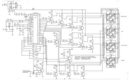
Clock diagram:
To enlarge a picture, simply click on it to enlarge it. And save the computer.
Not long ago I was faced with the task of either buying a new watch or assembling a new one myself. The requirements for the watch were simple - the display should display hours and minutes, there should be an alarm clock, and seven-segment LED indicators should be used as a display device. I didn’t want to pile up a bunch of logic chips, and I didn’t want to get involved with programming controllers. The choice was made on the development of the Soviet electronics industry - chip K145IK1901.
It wasn’t in the store at that time, but there was an analogue, in a 40-pin package - K145IK1911. The name of the pins of this microcircuit is no different from the previous one, the difference is in the numbering.
The downside of these microcircuits is that they only work with vacuum fluorescent indicators. To ensure docking with the LED indicator, it was necessary to build a matching circuit using semiconductor switches.
As string drivers – J1-J7 transistors can be used KT3107 with the letter index I, A, B. For drivers for selecting segments D1-D4, KT3102I, or KT3117A, KT660A, as well as any others with a maximum collector-emitter voltage of at least 35 V and a collector current of at least 100 mA will be used. The current of the indicator segments is regulated by resistors in the collector circuits of the row drivers.
A dot flashing at a frequency of 1 Hz is used to separate the hour and minute digits.
This frequency is present at the Y4 pin after the timing has started. This scheme also provides the ability to display on the display instead of hours and minutes - minutes and seconds, respectively. The transition to this mode is carried out by pressing the “Sec.” button. Returning to the hour and minute time display is carried out after pressing the “Return” button. This chip provides the ability to set two alarm clocks simultaneously, but in this scheme the second alarm clock is not used as unnecessary. A piezo tweeter with a built-in generator, with a supply voltage of 12V, is used as a sound emitter. The alarm clock signal is removed from pin Y5 of the microcircuit. To provide intermittent sound, the signal is modulated at a frequency of 1 Hz, used to indicate the second rhythm (dot). For a more detailed study of the functionality of the K145IK1901(11) microcircuit, you can refer to the documentation, which recently can be easily found on the Internet. The microcircuit must be powered with a negative voltage of -27V±10%. According to the experiments carried out, the microcircuit remains operational even at a voltage of -19V, and the accuracy of the clock is not affected at all.
The clock diagram is shown in the figure above. Chip resistors of standard size 1206 were used in the circuit, which makes it possible to significantly reduce the dimensions of the device. Any seven-segment indicators with a common anode are suitable.
Well, that’s the end of the story for now. It will be further developed and replenished. And I express my gratitude to its author, Evgeniy Fedorenko, for all questions and also give his email. Write to This email address is being protected from spambots. You must have JavaScript enabled to view it.


