In recent years, your HiFi or even High-End audio complex is less and less pleased with the detail, richness and transparency of sound? Are you considering upgrading your entire system? Or are you already looking for a quality network filter? If the latter - are you on the right track ????
Let's count?
In this century, the number of sources of electromagnetic interference in our homes is growing exponentially. Take a look around, try to count how many seemingly harmless light and small chargers, economical lamps, "electronic transformers" for halogens, computers, printers, and other electronics powered by mains and / or all kinds of "chargers" have come into your home over the past decade ? There were not enough fingers, even with my legs, my wife and ... this and that! ????
Today, perhaps 95% of mains power supplies are built on the basis of a high-frequency converter and do not use old bulky and heavy humming transformers at 50 (60) Hertz. Hurray, the green party is triumphant: most of these converters are very economical, compact and ... each one is impulse power unit a) whistles at the conversion frequency and harmonics and b) creates surges of the charging current in the input rectifier (very broadband interference - and straight into the network).
In truly high-quality (and expensive) switching power supplies, they struggle with interference very successfully, but still it is not enough for all the electrical junk they produce to remain invisible to the sensitive ears of a music lover. Why are there music lovers ... We have a good old 39 MHz radio telephone in our house. Gradually, he began to hum and hum so that I was seriously going to change the apparatus. But we use it relatively rarely, and the problem was once solved by itself, when, in pursuit of a beautiful sound, I cut all the switching power supplies to hell, along with computers in the house. After that experiment, by the way, these ones appeared with us.
So what should you buy?
In this article, I will not tell you which surge protector to buy. There are two reasons: for a reasonable price, I have not seen adequate filters; and those filters that I could recommend were completely incongruous, and they took up much more space than their function requires. Nevertheless, there is a solution: for skilled hands - to assemble the filters yourself, and I will try to explain its work so much that anyone who is friendly with a soldering iron can equip their equipment with adequate protection against electromagnetic interference penetrating from the mains. If you do not have the opportunity, or the desire to breathe rosin, show the article to a friend who can help you.
Competent manufacturers should have foreseen everything!
Fig-you! (the hut is such an Indian (c) cat Matroskin)
We open the CD-player, which was bought at one time for six hundred "green" ones. And what we see: there is a rudimentary surge protector here, but alas, only silk-screened on the board, they saved money on the choke and capacitors. I fully admit that in their listening rooms, with ideal power filtering, that filter was not needed - the "gurus" did not hear the difference from the lack of a filter. Well, they brought in "ratsuha" - the device went to the masses naked and defenseless against the new generation of electronic houses ...
Get to work!
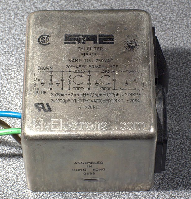 In principle, the industry produces high-quality filters. Only they cost a little too much. A kind of fully shielded boxes with a schematic on the side. There are coils, capacitors. Let's figure out what is there for what, and assemble it ourselves from the available parts. By the way, in defiance of audiomaniacs, I argue that a competent surge protector in a device, assembled from high-quality conventional (not audiophile) components, is much more effective and "sounds" better than any of the most esoteric power cables, as well as most "audiophile" filters nutrition. Argue? ????
Tell me who is your enemy
1) Differential interference voltage. This is such a "harmful" signal that comes along with a "useful" supply voltage (or signal), it is measured between two connecting conductors, "hot" and "common" wires, or, more simply, between two power rails.
2) Common mode interference voltage. This signal is measured between the instrument body (ground) and any connecting conductor. The peculiarity of this interference is that it will be identical on both power wires, i.e. unlike differential noise, it cannot be caught between the wires and it seeps inside bypassing conventional filters.
Blocking capacitor
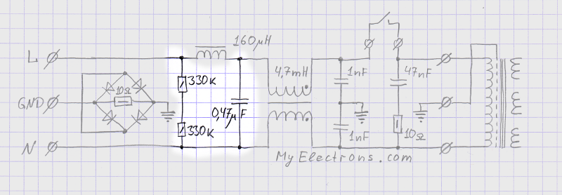 The capacitor bypasses the differential RF interference and does not let them further into the apparatus. We must not forget to discharge it when turning off the device, otherwise, by accidentally grasping the plug, you can get a very tangible "motivation". To do this, we put a resistor peacefully warming up in normal operation. Oh, do not lead me friendship with the "green" ...
Throttle
 The inductance (an ordinary small choke) forms an L-shaped LP filter with a capacitor. We are not very interested in the specific cutoff frequency of the filter. The choke is thicker (if only it was designed for a constant current several times higher than the current consumed by the device), a larger capacitor for a voltage of at least 310 volts - and everyone is happy.
Common mode transformer
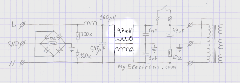 The windings in such a transformer are identical and are turned on in the opposite direction, so it freely passes everything that comes as a potential difference between L and N. Otherwise, it can be explained as follows: the normal load current creates opposite identical fields in the core, which are mutually compensated. Then why is all this - you ask?
The core of such a transformer remains non-magnetized by the main load. If we imagine the supply wires L and N together as one wire, then we have a considerable inductance on the path of the common-mode noise, i.e. everything that is induced on both wires at the same time. The wires are those, whether it be a regular power cable for a dollar, or an exotic audiophile miracle - the essence of an antenna that receives both the Mayak station and everything emitted by household electronic stinks. Inside the audio unit, we don't need in-phase interference either: through the capacitive connection, it can penetrate into the intestines of our pets very aggressively.
Two little companions
 Two small capacitors to the common-mode transformer company. They short-circuit the common-mode noise to the protective ground and create, together with the common-mode transformer, a kind of L-shaped filter for common mode noise, do not let it go further into the apparatus. Without them, common-mode interference, even if it met considerable resistance from our transformer on its way, will still go to look for its victim inside the apparatus.
Antizone
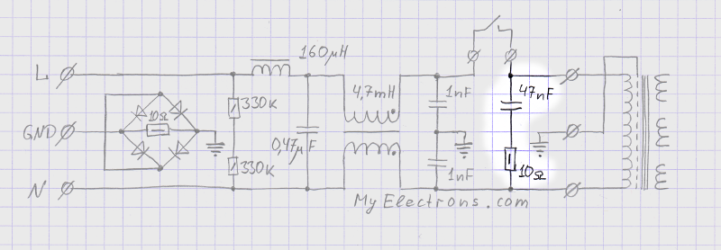 Anti-ringing chain, or RC-Zobel chain. A somewhat mystical animal, but very useful. Here, together with the primary winding of the transformer in the apparatus, we form an oscillatory circuit with a low Q factor in order to "catch" what will "jump out" from the primary when the power is turned off. Spark arrester. Protection of the rest of the filter and the transformer itself from self-induction EMF when disconnected at an unfortunate moment (with a large current through the primary). It also contributes to the conversion of HF interference into heat.
There would be no capacitor - such a low-resistance resistor would simply explode from the mains voltage. If there were no resistor, we would get a relatively high-quality circuit together with the primary and / or filter choke.
Another point of view: we introduce a purely resistive and very low-resistance component of the load impedance at the RF ... Who can explain better - please, I will put it "in a book" with preservation of the authorship ????
#ground_loop
We break the ground loop
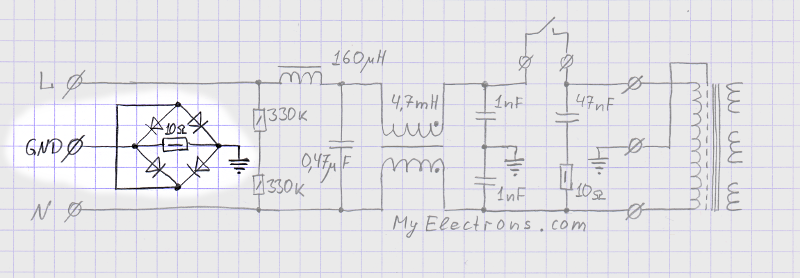 Resistor in parallel with back-to-back diodes. In another version, it could be a choke. Included is this case between the protective earth and the body of the device. Why, you ask - it seems to have nothing to do with filtering interference? Let's figure it out.
Oppositely connected diodes will successfully short-circuit any high-current leak inside the device case (what short, breakdown) to protective ground. Thus, we comply with the safety requirements: in the event of an accident, no voltage hazardous to human life and health should appear on the device case. In this case, the diodes "break" the circuit for low voltages.
The resistor creates a path for small currents. If it were not for it, and the internals of the device are well decoupled from the ground, then even small leaks would create an excessive voltage swing on the case relative to the ground, and all this would penetrate the device through capacitive couplings.
So why should the protective earth be “untied” from the body anyway? The fact is that voltages can be induced on the protective ground: for example, by the same common-mode noise that we filter out. Also, alas, such a wiring of the network is often found when the protective ground is at the same time a return wire for the actual voltage of the network. In this case, even with a small wiring resistance, a considerable consumption current creates a noticeable voltage drop. All these factors can "accelerate" under normal conditions up to tens and even hundreds of millivolts of potential differences between the protective grounding of different units. Now, if we transmit the audio signal through the connections wired with one wire to the body (RCA bell connectors, unfortunately so popular in household HiFi), then this very potential difference between the instrument cases will be directly mixed into the signal.
In total, by uncoupling the device case (and in most cases this also means the signal ground thereof) from the protective ground, we thereby significantly reduce the mixing of any "eccentricities" that can happen in the outlet - straight into the signal. Of course, a self-respecting fan of high-quality sound reproduction will use exclusively balanced connections that are immune to common mode noise. Only, alas, I still have not all devices connected exclusively with balanced cables. And what about you, dear reader? ????
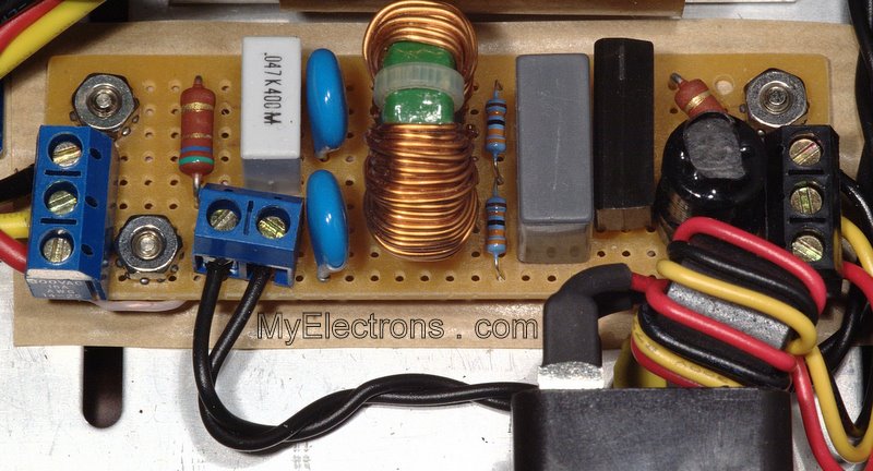
We collect
The power switch is attached according to the principle - where there will be less spark. The rest of the filter does not differ much from what is used in expensive computer power supplies. By the way, from there you can get hold of the details.
The proprietary apparatus that I mentioned at the beginning of the article also received its own dose of filtration, details.
Better yet, can you?
Can! Extremists turn on huge transformers "opposite" and filter everything in the low-voltage part. The result is slightly better, the budget is orders of magnitude higher.
Or perhaps you would like to give your best music lover friend an inexpensive gift for which he will be sincerely grateful to you? ???? Weigh the pros and cons, and make the right decision! ...
This entry was posted in, by. Bookmark the.


