A. MUSIENKO,
As you know, a lot of fires occur due to various electrical appliances left unattended. These are heaters, TVs, and so on. The device "Leaving, turn off the light" - UGS-1 serves to indicate the presence of switched on electrical appliances. It is connected in series to the circuit of power consumers (Fig. 1).
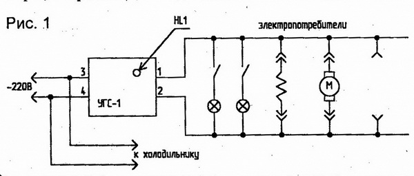
The UGS-1 diagram is shown in Fig. 2.
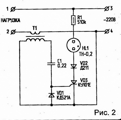
When the appliance is switched on, the neon lamp HL1 is on. If all consumers are turned off, the neon will not light up. It is advisable to install UGS-1 near the exit door.
UGS-1 itself practically does not consume current, and the total current of consumers connected through it can reach 6 A.
Radio amateur 8/97
Socket with load indicator.
A. OZNOBIKHIN, IrkutskEquipping a conventional socket with the proposed LED indicator can increase the usability of this most common electrical appliance. The indicator will not only show that the network is working and help you find the outlet in the dark, but will also change the color of the glow if a load is connected to the outlet. A tripping as a result of an overload of the fuse built into the socket is signaled by a flashing red LED.
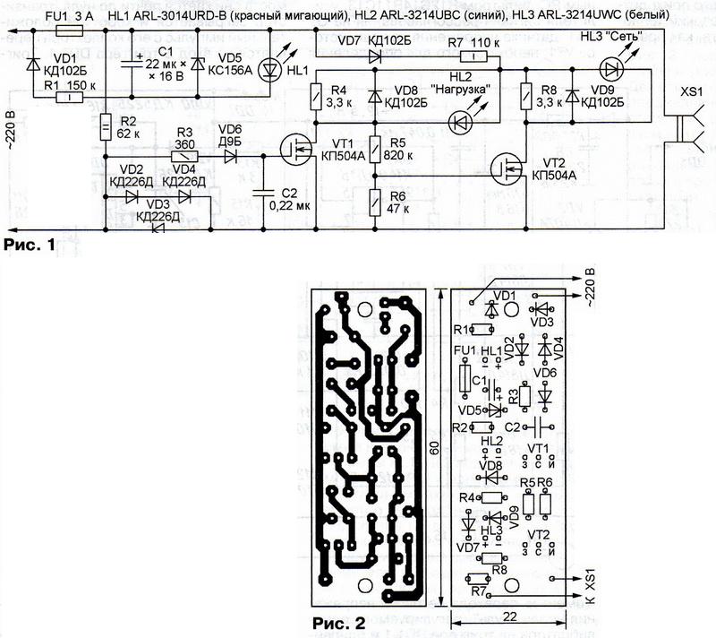
It is advisable to equip such an indicator with those sockets to which power-supplied devices are connected that do not have their own power-on indicators and fuses. A device assembled according to the diagram shown in Fig. 1, should be placed inside the XS1 socket housing, and if there is not enough space in it, next to the socket in a separate housing.
In the event of a fuse FU1 burnout, the mains voltage will be applied through the resistor R2 and the load (if connected) to the elements VD1, R1, C1, VD5 and HL1 previously shunted by the insert. The VD1 diode passes only the direct half-waves of the mains voltage for it, which, through the current-limiting resistor R1, charge the capacitor C1 to the stabilization voltage of the Zener diode VD5. This voltage is sufficient for the operation of the flashing LED HL1, signaling a malfunction.
Until the load is connected to the XS1 socket, no noticeable current flows through the VD2-VD4 diodes, the voltage drop across them is close to zero. Therefore, the capacitor C2 is discharged and the field-effect transistor VT1 is closed. The HL2 LED located in its drain circuit does not light up. But the voltage across the resistor R6 is enough to open the transistor VT2. A current flows in its drain circuit. Lights up, indicating the presence of voltage in the network and helping to find the outlet in the dark, LED HL3.
If the load is connected to the XS1 socket and consumes current, its negative half-waves flow through the VD3 diode, and the positive half-waves flow through the VD2 and VD4 diodes connected in series, the voltage drop across which is sufficient to charge the capacitor C2 through the resistor R3 and the VD6 diode to a voltage at which transistor VT1 will be open. The HL2 LED will turn on, signaling the presence of a load, since the voltage between the drain and the source of the transistor VT1 will decrease practically to zero. The voltage between the gate and the source of the transistor VT2 will also become zero. This transistor will close, turning off the HL3 LED.
It should be noted that the operation of the indicator from a load of only 1 W was achieved due to the low (only 0.6 V) threshold voltage of the KP504A field-effect transistor (VT1). You should not replace this transistor with another. But a transistor of the same type in position VT2 can be replaced with KP501 A.
The maximum power of the load connected to the XS1 socket depends on the permissible forward current of the VD2-VD4 diodes. For diodes of the type indicated in the diagram, the current should not exceed 1.7 A, and the load power - 500 ... 700 W.
Diodes KD102B can be replaced with KD105B or other rectifiers with a permissible reverse voltage of at least 300 V, and the D9B diode - with another germanium of the same series or, for example, D2 series. Instead of a Zener diode KS156A, any low-power one with a stabilization voltage of 3.9 ... 5.6 V is suitable.
LEDs of the types indicated in the diagram can be replaced with others with similar characteristics, choosing the color of their glow according to your own taste. It is only necessary to remember that the one who will use the outlet must develop stable associations between the color of the indicator light and the situation.
The flashing LED (HL1) can be replaced with a regular non-flashing one. In this case, the capacitor C1 can be excluded from the device, and the VD5 Zener diode can be replaced with a conventional diode, turning it on in the same direction. LEDs HL2 and HL3 can be replaced with one two-color three-pin, or even use two crystals of different colors in a multi-color LED. It is not possible to replace all three LEDs (HL1 - HL3) with one full-color one without noticeable complication and alteration of the circuit, since the pairs of LEDs have common cathodes. The desired brightness of the LEDs HL2 and HL3 can be achieved by selecting the resistor R7, however, it is undesirable to set it less than 22 kOhm due to too much heat dissipation.
A variant of the printed circuit board of the signaling device intended for installation in the housing of a power strip with several outlets is shown in Fig. 2. Capacitor C1 - K50-35, C2 - any ceramic or film.
If you reduce the size of the board a little, it can be built into a wall outlet for exposed wiring.
If there is not enough space inside a wall-recessed socket, the signaling device can be designed as an adapter plugged into such a socket.


