and reassembling the iron.
Do-it-yourself iron repair
So, your iron has broken down at your home, no matter from which manufacturer, the question arises: "How to fix the iron."
Testing of the electrical circuit, as for all household appliances, is carried out with a probe \ for example OP-1 \
or with a digital multimeter.
There is no significant difference in the schemes of irons from different manufacturers.
Iron scheme
For a general presentation, consider a sequential electrical circuit of connections iron Philips
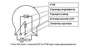
The first wire of the phase or zero potential from an external power source has a plug-in connector with the terminal, from the terminal through the thermostat, the wire goes to the heating element. The second wire from the external power source has a contact detachable connection with the second terminal, from the second terminal the electric circuit has a serial connection passing through a thermal fuse and closes at the second terminal of the heating element. The control lamp and the fuse are connected in parallel to the two contact connections of the heating element.
The electrical circuit is closed on the heater - heating element and light bulb. The thermostat sets a certain temperature regime for heating the iron.
Closing and opening of the electrical circuit occurs in the thermostat itself due to a change in the bimetallic plate under the influence of the heating and cooling temperature of the heating element. The reasons for the malfunction of the iron are as follows:
- a break in the cord wiring at the base of the plug;
- mechanical damage to the wiring of the cord along its entire length;
- burnout of the heating element \ iron soles \;
- oxidation of the contacts of the bimetallic plate of the thermostat;
- blown thermal fuse
What can be replaced here during testing:
- replace the cord;
- replace the plug of the cord;
- clean the thermostat contact;
- replace the thermostat;
- replace thermal fuse
Replacing the heating element in case of its malfunction, which is the sole of the iron, does not make sense, since the sole of the iron itself is more than half the cost of the iron itself. In this case, the sole of the iron is thrown away, everything else from the iron goes to spare parts. When dismantling / disassembling / ironing, care should be taken to avoid damaging the iron body.
It should be remembered that testing for detecting a malfunction of the iron is carried out in a passive way without connecting to an external power source. Immediately before connecting the iron to an external power source, it is necessary to measure the total resistance of the electrical circuit with a digital multimeter, which should not be zero on the device display.
Iron repair - moulinex
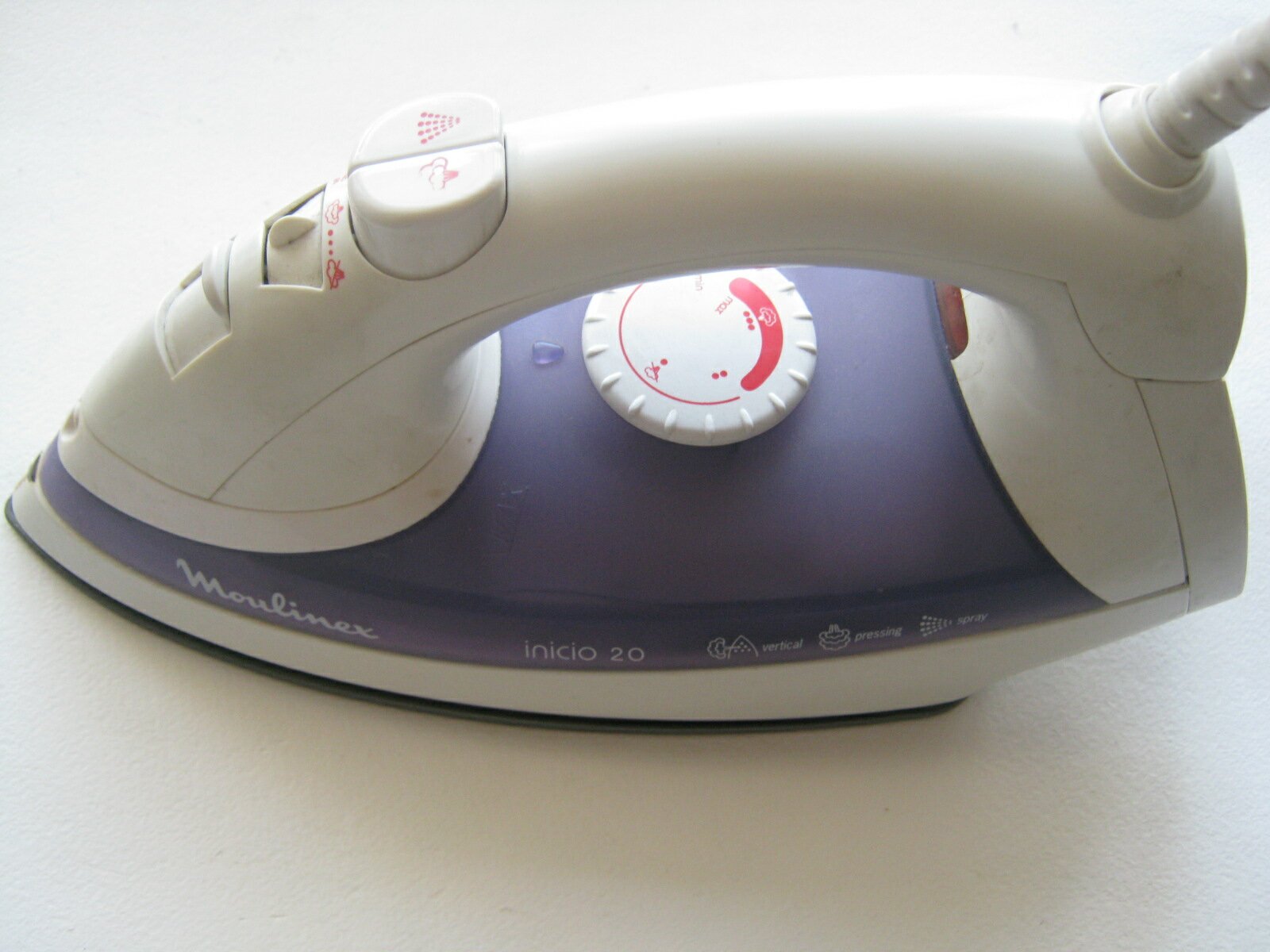
This topic is supplemented with personal photographs and an accompanying description of the repair of the iron. As an example, consider a malfunction of the Mulinex iron.
Photo-with explanations
So, before us is the Mulinex iron and the reason for its malfunction is unknown to us in advance, that is, we need to establish the exact cause of its malfunction.
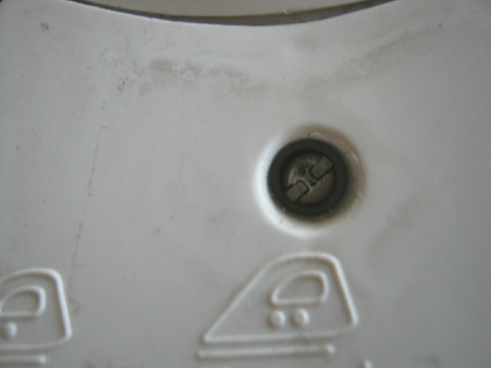
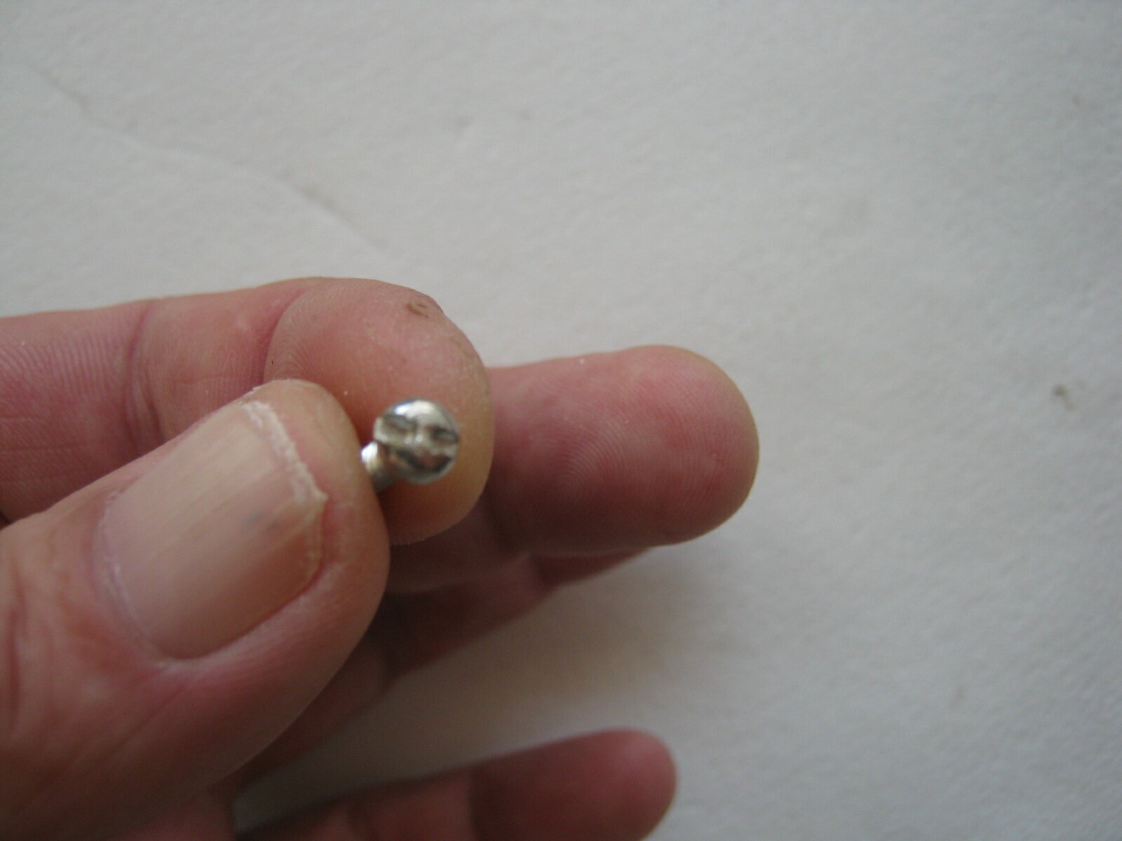
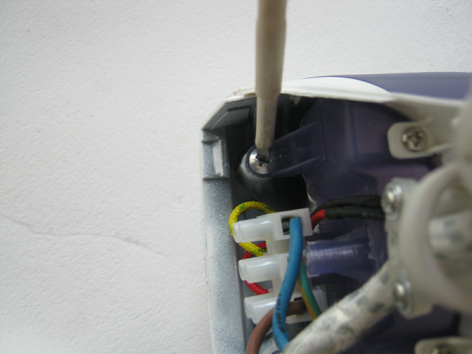
In the back of the iron \ photo # 1 \, to remove the cover, you need to unscrew the screw. The screw head, as you pointed out, is not suitable for our domestic screwdrivers. How to get out of the situation if there is no similar screwdriver? - Here, too, you can find a way out, for this we need small scissors with sharp ends. We insert the two ends of the scissors and we can easily unscrew the screw.
After unscrewing the screw, carefully open the cover with a screwdriver \ photo # 2 \. At the same time, we try not to damage the lid body.
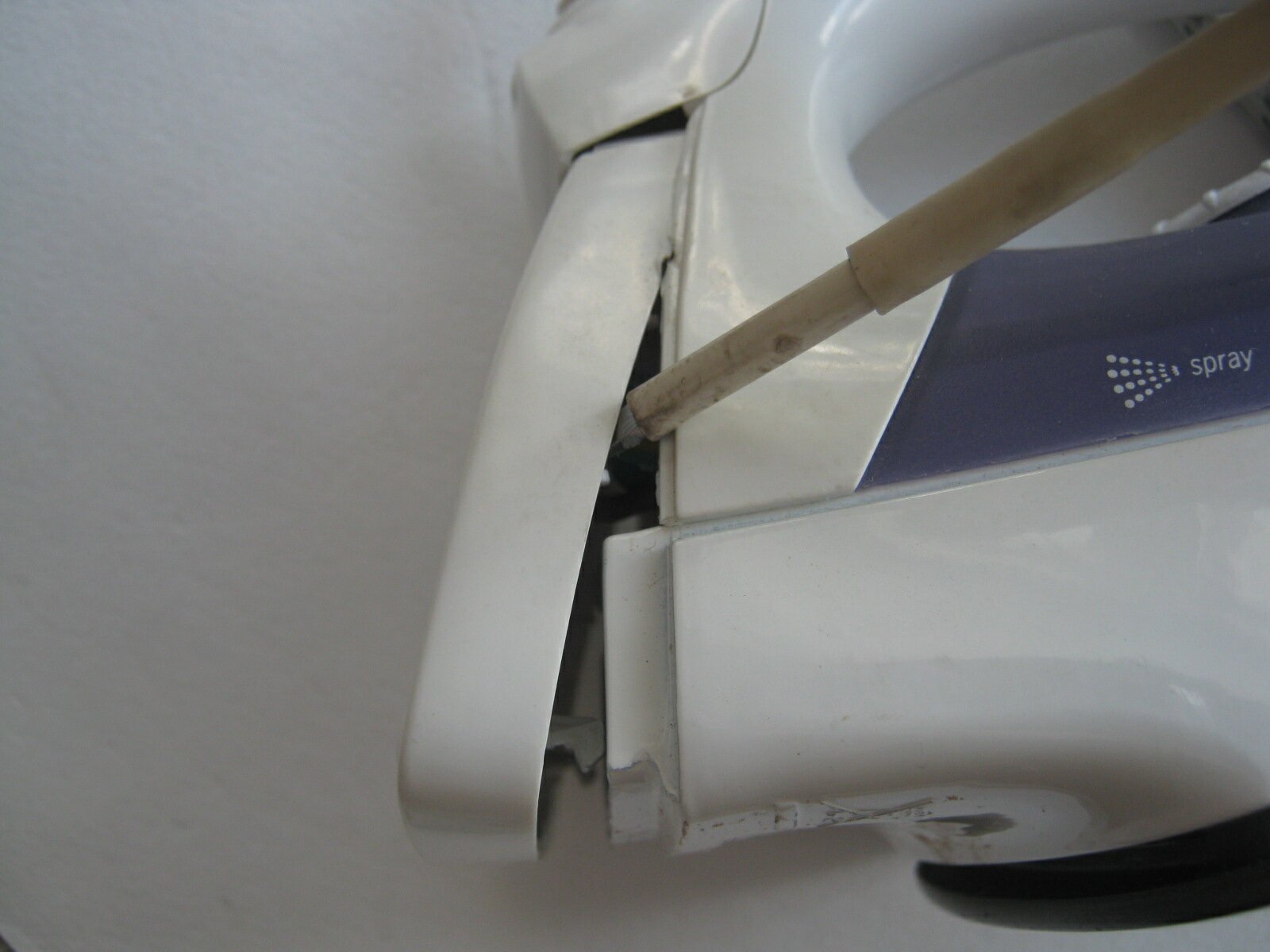
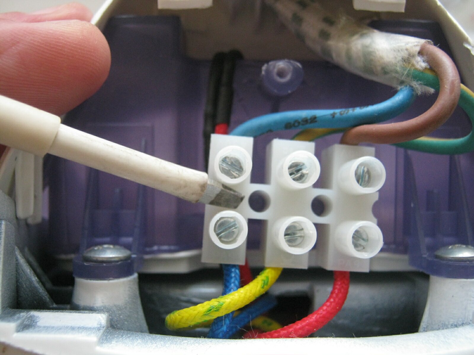
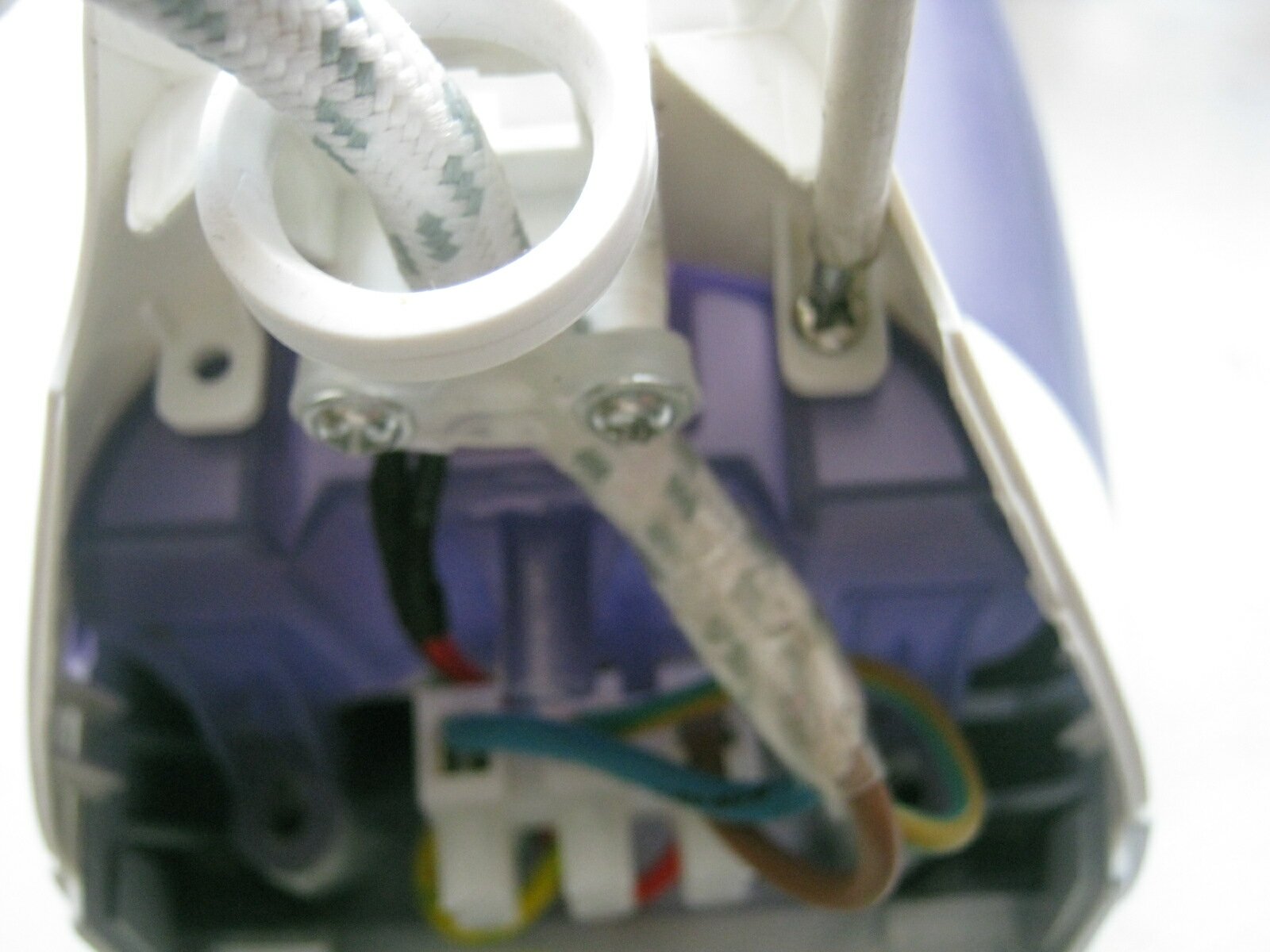
After removing the back cover of the iron \ photo No. 3 \ we can see the terminal connection of the wires of the network cable with the iron elements:
thermostat;
heating element \ heating element \.
To directly get to the contacts of the thermostat \\ photo No. 5 \ and the heating element, or in other words - the sole of the iron, we turn off the parts one by one.
For beginners, you should remember the sequence of such disassembly so as not to create confusion for yourself in the further assembly of the iron.
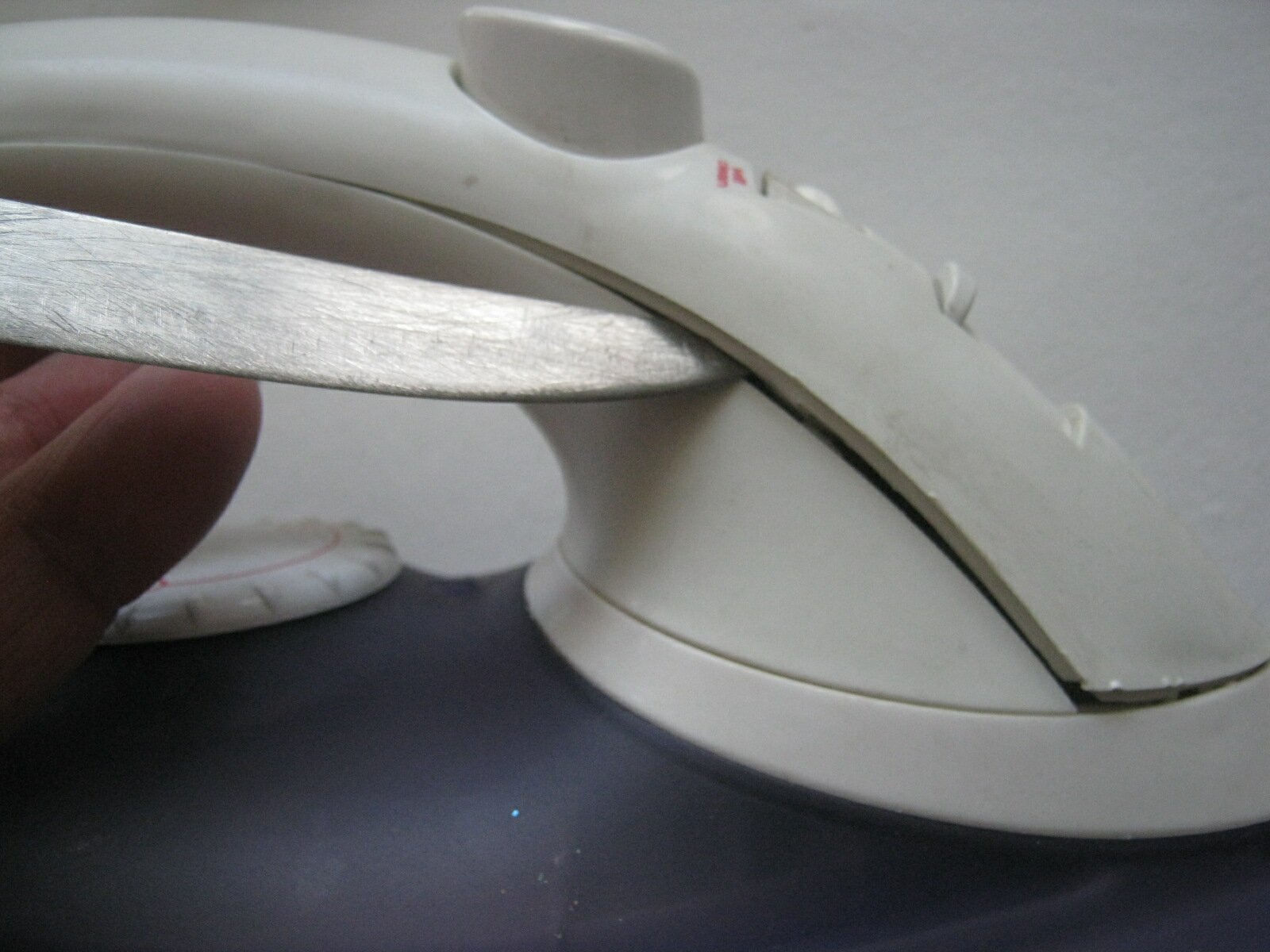
The screwdriver in the photographs shows the attachment points for such parts.
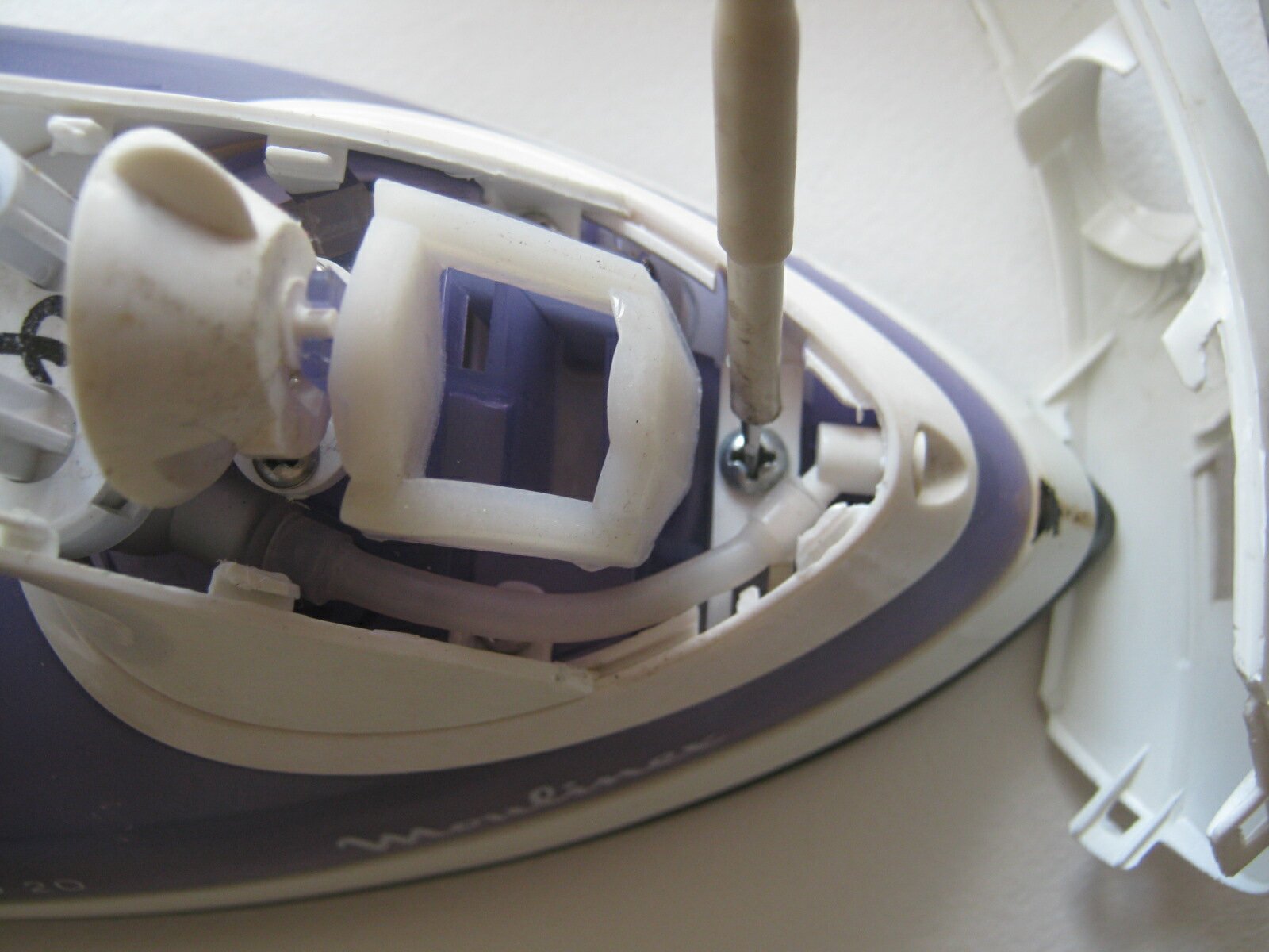
That is, here you need to be careful about disassembly, as it were. The body and individual parts of the iron are supplemented with fasteners such as latches.
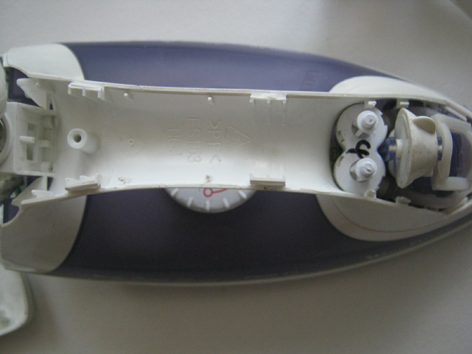
A screwdriver shows the handle of the thermostat \ photo # 7 \ and we need to remove one more cover, which is the heat sink of the iron plate.
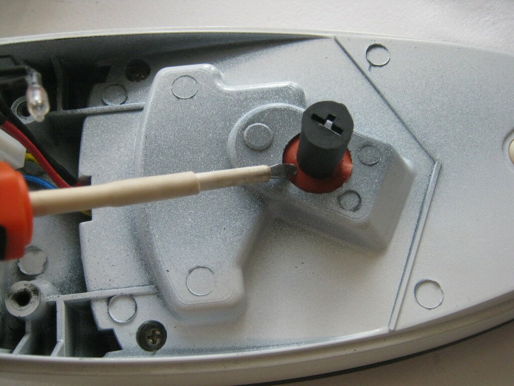
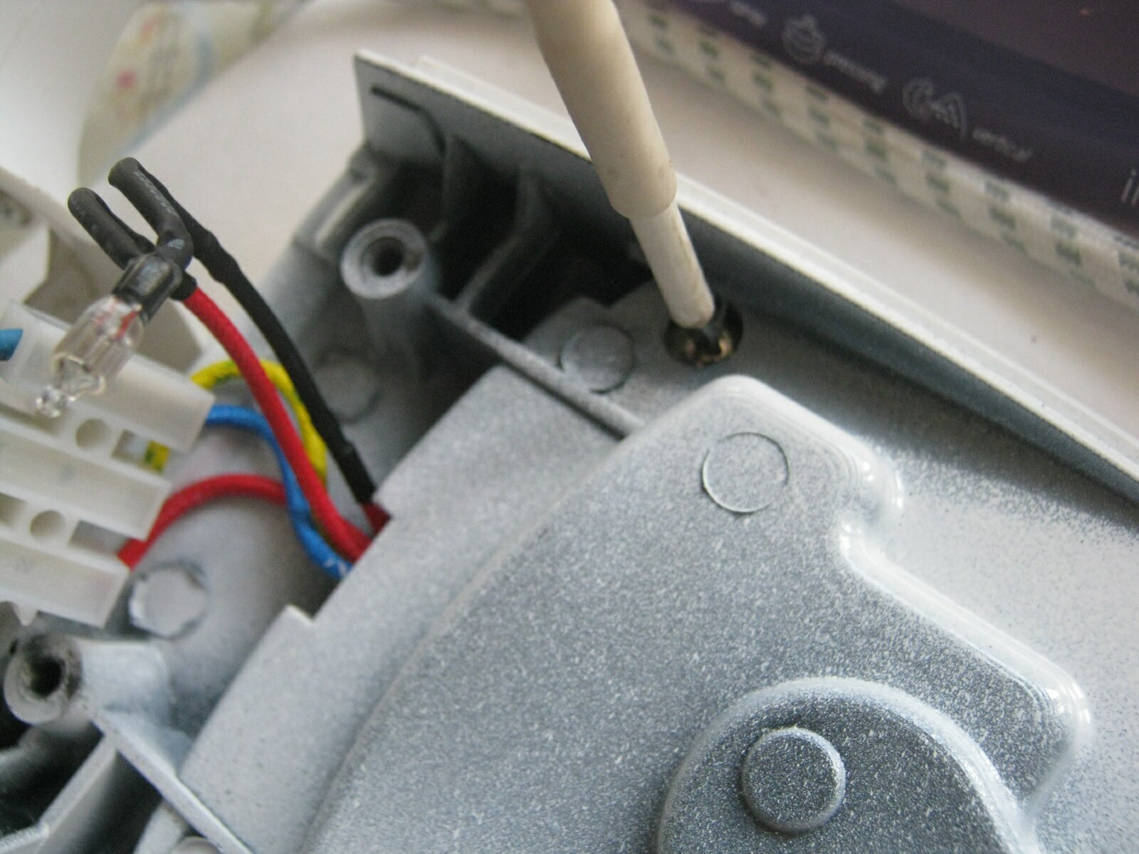
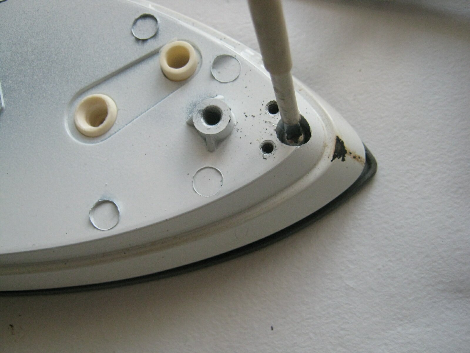
The photo shows additional places of such connections \ photo No. 8 \, we also continue to unscrew the screws and free the sole of the iron from the cover.
Well, here we are, so to speak, to the most interesting - the contacts of the thermostat \\ photo # 9 \\. The thermostat contacts are indicated with the tip of a screwdriver.
The thermostat knob sets the heating of the iron soleplate set by us. In order to prevent overheating of the heating element, the thermostat design has a bimetallic plate, which, upon reaching the preset heating temperature, disconnects the contacts. As the bimetallic plate cools down, the electric circuit closes and the sole of the iron heats up again.
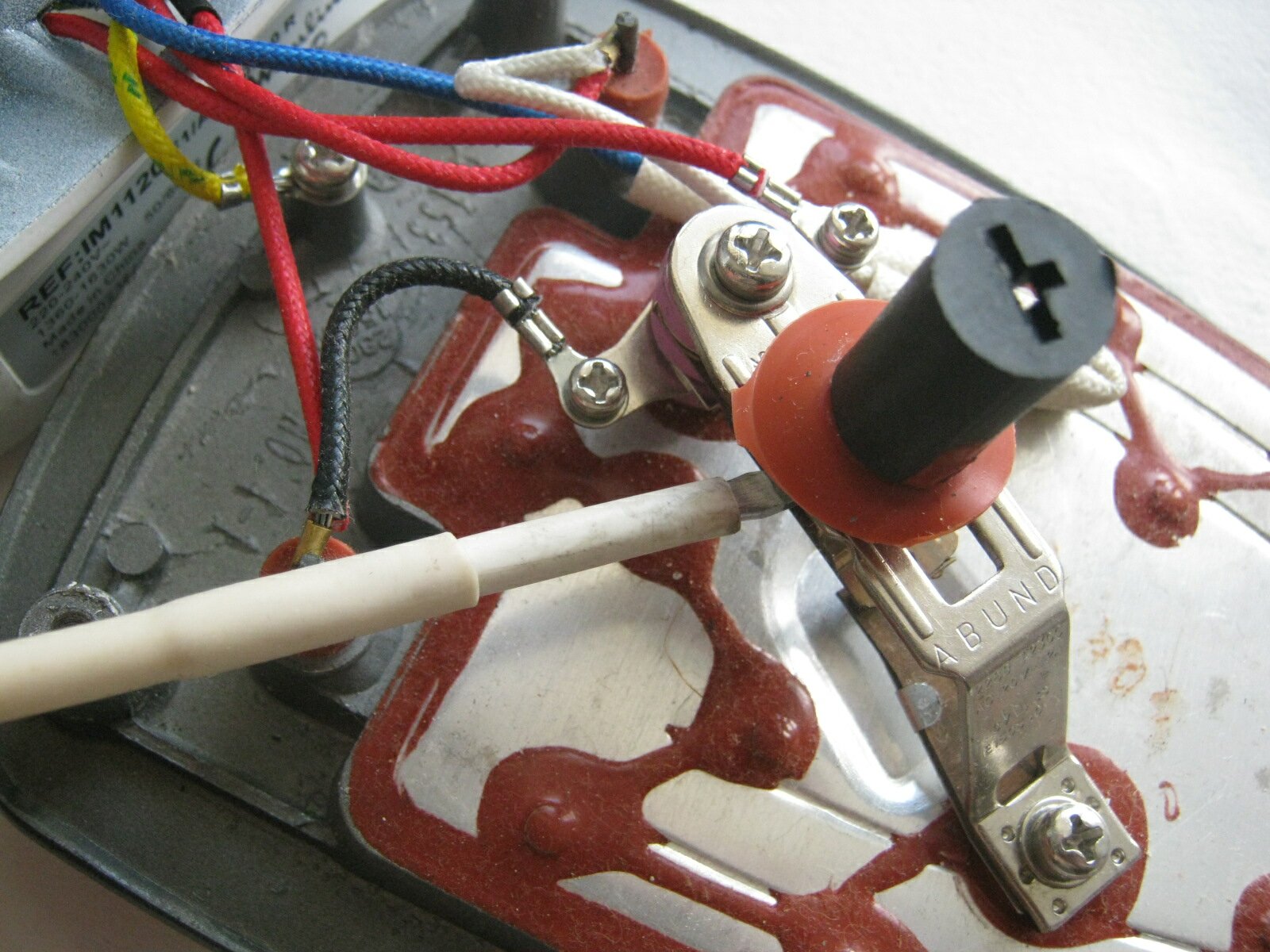
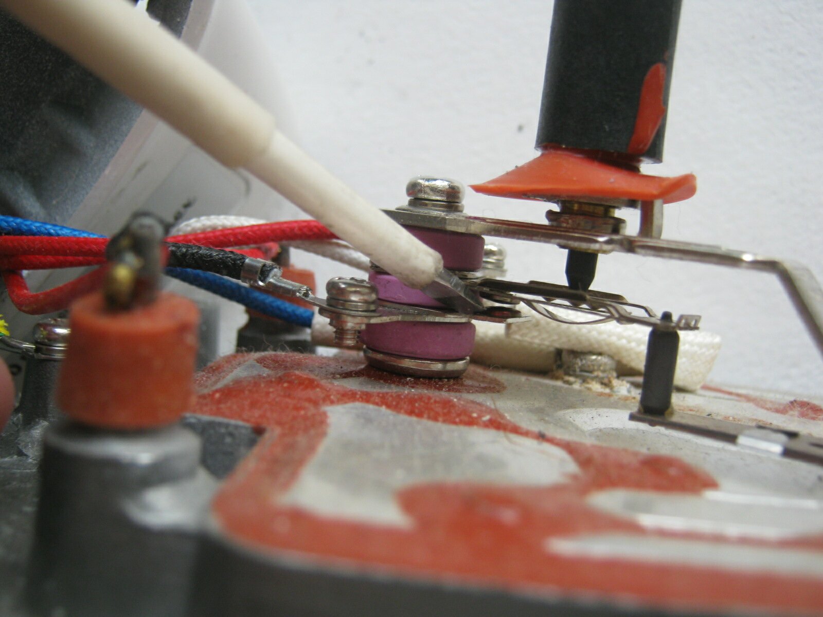
We carefully inspect the contacts of the thermostat, that is, we check this section of the electrical circuit with a probe.
For this example, the iron malfunction was the oxidation of the thermostat contacts. We clean the contacts of the thermostat with a piece of fine emery paper and once again carry out diagnostics with a probe for this area.
In addition, of course, you should also check the heating element of the iron itself.
Iron diagnostics
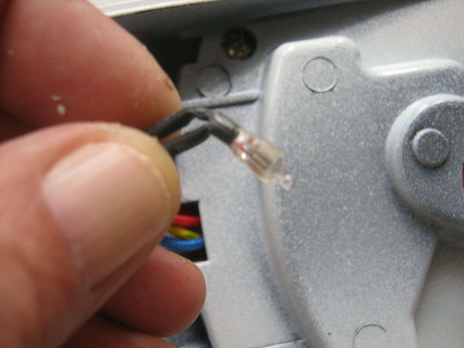
The photograph shows the signal llama \ photo # 10 \. The lamp in the electrical circuit is connected in parallel and if it burns out, this does not entail a malfunction of the iron as a whole.
In this photograph, the fingers of the hand show the contacts of the heating element \\ photo # 11 \\. We carry out diagnostics of the heating element.
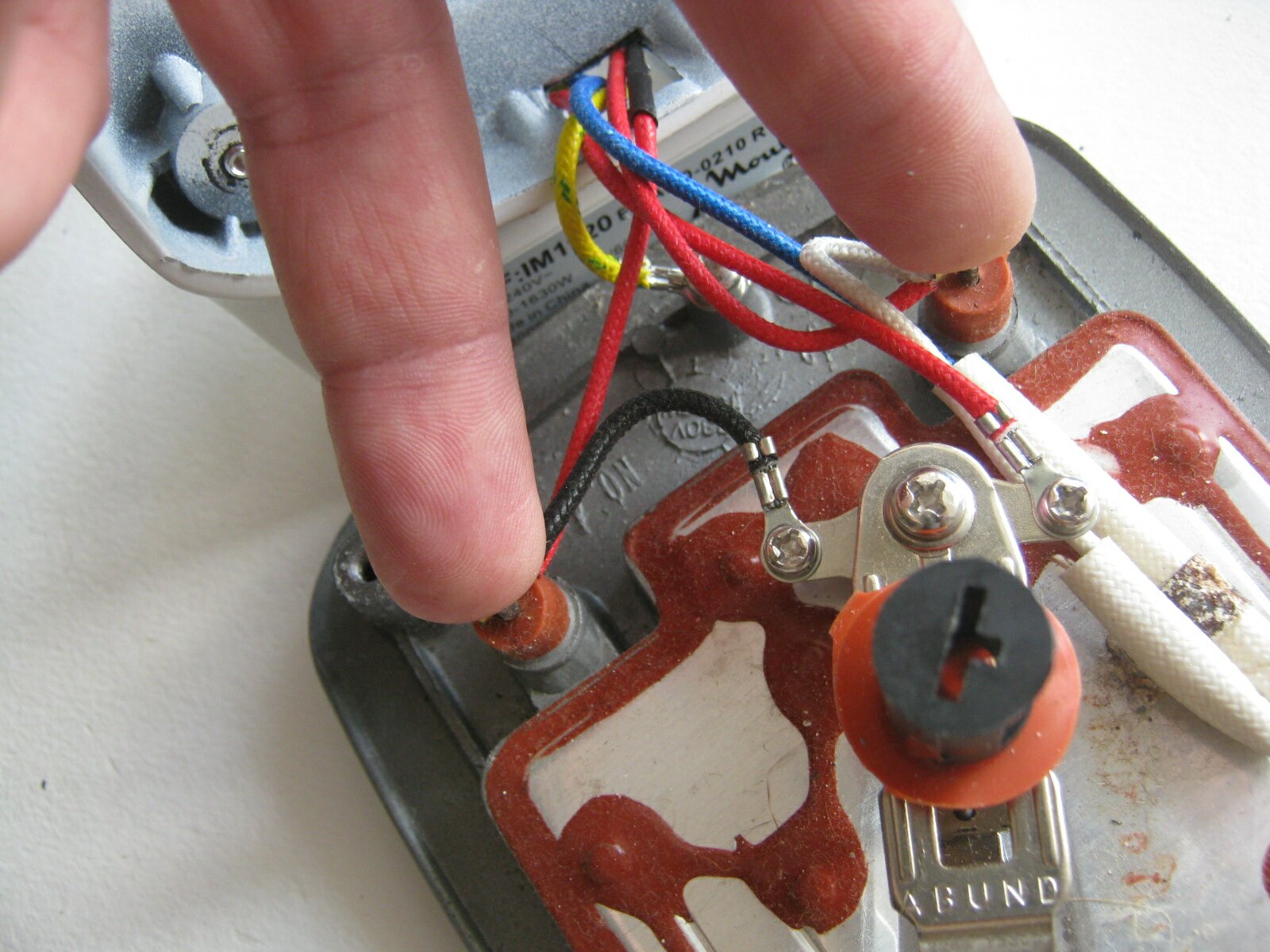
To do this, set the multimeter to the resistance measurement range. With two probes of the device we touch the contacts of the heating element, on the display of the device we can see the resistance reading - 36.7 ohms.
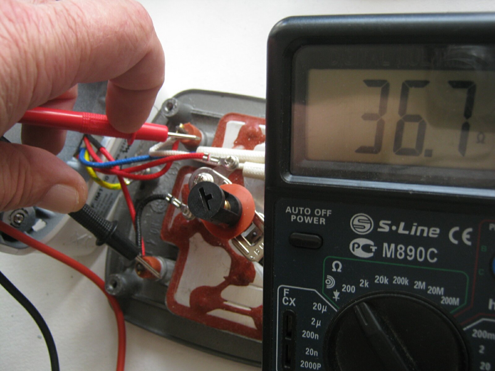
The meter reading corresponds to the resistance of the heating element. We carry out diagnostics for the general electrical circuit of the iron \ photo No. 13 \.
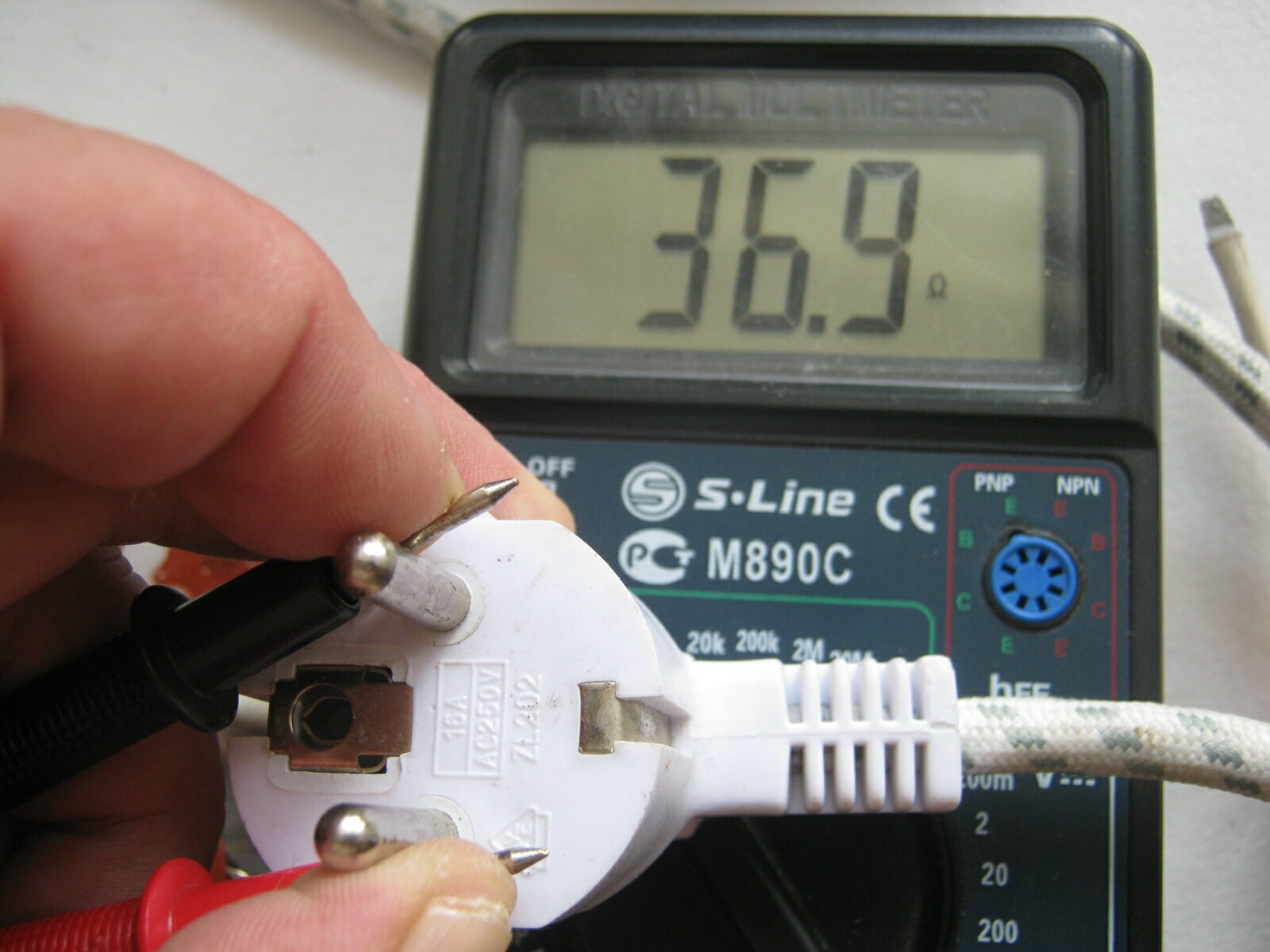
We connect two probes of the device with the pins of the plug, the result is clearly visible to us on the display of the device. That is, the resistance reading for the general electrical circuit of the iron is two tenths more.
So we figured out the malfunction and fixed the iron. As you have seen, we cannot do without diagnostics both for individual areas and for diagnosing the circuit as a whole.
The topic will have an addition in the future.


