It would seem, what could be interesting and new in measuring temperature using Arduino? Hundreds of articles have been written, tens of megabytes in size, maybe a little less, and maybe a little more sketches ... And here's my article. What for? To be honest, I also thought that this question was “chewed up and down” until I myself faced the measurement of temperature. And then it got up. Something doesn’t work, something doesn’t work, there are a lot of questions, to which the answers have to be “scratched out” by interrupting half of the Internet, and not only the Russian-speaking one. This article, unlike my previous articles on this resource, is much more practical, but let's start over. Why, in fact, measure the temperature with something new, when thermometers are sold - for every taste and budget? And the fact is that the temperature, often, has to not only be measured, but then, based on the data obtained, do something, or simply register in order to track changes. Connecting, using , a thermal sensor with a relay unit, we will get the simplest thermostat, and if this thermostat can monitor the temperature at several points (zones) and act according to a certain algorithm, we will get a rather serious device, the industrial analogue of which is comparable to the cost of a good laptop. However, the purpose of this article is not to create sophisticated devices. The goal is different - to offer the beginner a simple, field-proven temperature measurement solution. Also, like the previous articles, this one will consist of parts. Each of which will consider its own question. The parts will go in increasing difficulty.
Part one. The simplest, but also useful
So, from words to deeds! To implement this project, at the first stage, we need a digital thermal sensor DS18B20, ARDUINO UNO, a 4.7 kΩ resistor (the power does not really matter, from 0.125 to 2 W is entirely suitable, but the accuracy matters, the more accurate the better), a piece 3-core wire (and separate wiring at the stage of the experiment will also work), and also a few pins for the board. Although it is also possible without them, if carefully, of course. The choice of this sensor is not accidental. The fact is that it can monitor the temperature in the range from -55 ° C to + 125 ° C with an accuracy in the main part of the range of 0.5 ° C, which is quite enough to control both domestic heating and various freezing and refrigeration units, as well as baths, saunas , greenhouses, incubators, nurseries and others. Let me remind you that ARDUINO UNO can be freely purchased here: or here: , thermal sensor DS18B20 - , although personally for me - this: the advantage of mine is its small size, comparable to the size of the cable. Disadvantages - the absence of a board, which in some conditions negatively affects the convenience of installation and the viability of the sensor. Also - at the sensor a resistor is built-in and no more resistors need to be soldered, but the ability to connect several sensors "in a chain" disappears. The connection of the sensor to the Arduino can be seen in Fig. 1 and indicated in Table 1. It is easy to identify the contacts on the thermal sensor. You need to take it so that you look at the cut with numbers, and the legs were at the bottom. The leftmost leg will be GND, the middle DQ, and the rightmost VDD.
Table 1.
Pin Arduino Uno |
Note |
|
5V, one leg of the 4.7 kOhm resistor is also soldered. |
||
Figure 1. Connecting one thermal sensor.
The figure shows that two resistors were used. This is due to the fact that the resistor I found with the marking "4K7" actually had a rather high error, which I had to compensate for with the second resistor. The total resistance of this assembly was 4.695 kOhm, which I think is quite acceptable. You can also see in the figure that the sensor is not soldered directly to the wires (a cut of the loop), but is inserted into the connector. This was done for reasons of the development of the experiment. It is highly recommended to solder these sensors. The sketch itself is also quite compact:
Only 14 lines of code with comments. Any beginner will be able to figure it out. As a result of the work, the program will give something like this:
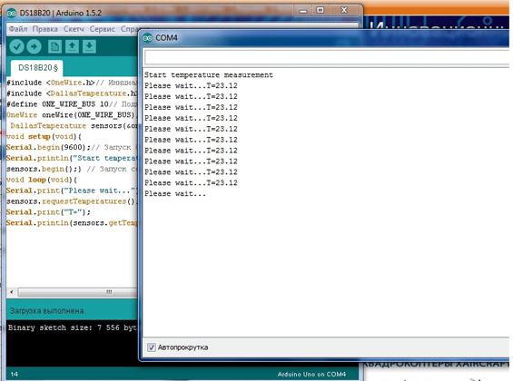
Figure 2. Result of work with one sensor.
Part two. A little complicated.
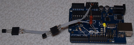
We'll complicate this part by adding another sensor. Suppose we need to measure the temperature outdoors and indoors. To do this, we just add one sensor "in a chain". Very much like a parallel connection. Electrical connoisseurs will understand what I mean. But there is a difference: in this case, the leads from the center wire should be as short as possible.
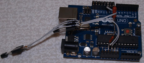
Figure 3. Board with two sensors.
The sketch has grown by only 3 lines. Now it has 17 lines:
The results of this sketch can be seen in Figure 4.
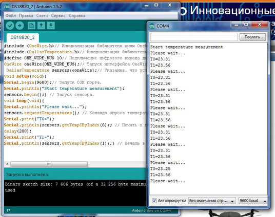
Figure 4. Working with two sensors.
Part three. Final.
Now let's connect an LED to Arduino, which will light up when a certain temperature is reached. Such a "threshold signaling device". This requires a conventional LED and a current-limiting resistor. I got a hand on 100 Ohm, and I used it by connecting it to the 7th pin of Arduino. We solder the long leg of the LED (anode) to the resistor, and connect the short leg (cathode) to the GND pin of the Arduino. You should get something like Figure 5.
The sketch also did not grow much at all:
The operation of this program on the computer is displayed in exactly the same way as shown in Figure 4. Naturally, the sensors.getTempCByIndex variable (1) can be operated within a very wide range and LED control is just the simplest example of all possible.
And in conclusion of this article, one more step. Now I will tell you how to connect several "garlands" of these devices to one Arduinka. The fact is that the length of the "garland" cannot be infinite; moreover, it is very limited. In ideal conditions it is 300 meters, but creating “ideal” conditions is a rather expensive pleasure. In real conditions, it is not recommended to exceed 10 meters. For an ordinary "room" thermometer, this is more than enough, but if we are talking about any more serious equipment, this is too little. Moreover, for stable operation, it is necessary that the sensors are located as close as possible to the bus conductors - a "garland". Rejection, of course, is also possible, but the accuracy and noise immunity in this case will be extremely low. So, we connect several "garlands" precisely in order to collect information from a large number of points, while maintaining sufficient accuracy and noise immunity. Add contacts according to table 2:
Pin Arduino Uno |
Note |
|
5V, one leg of 4.7 kOhm resistors is also soldered. |
||
Digital input, the second leg of the 4.7 kOhm resistor is also soldered. |
||
Digital input, the second leg of the 4.7 kOhm resistor is also soldered. |
As you can see from the table - there is nothing complicated, exactly the same bus, only on a different digital water. I did not solder to pin 9 only for reasons of convenience and soldering speed.
Sketch:
The sketch hardly needs any unnecessary comments.
The result of the sketch looks like this:
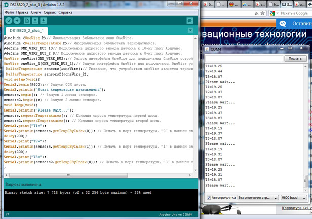
Figure 6. Simultaneous operation of two sensor lines.
And the board with two lines connected looks like this:
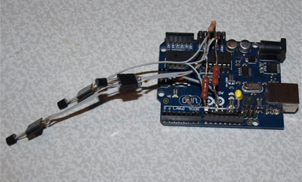
Figure 7. Board with two buses.
It can be seen from the figure that the 4.7 kOhm resistor is also made composite to improve accuracy.
The libraries used for writing the sketches discussed in the article are located here:
Review prepared by Pavel Sergeev


