Diagram of a homemade low frequency power amplifier (UMZCH) on TDA2050 microcircuits, output power up to 25W per channel. The amplifier is made on two TDA2050 microcircuits. There are no more active elements in his circuit.
The high gain of the TDA2050, which allows an output power of up to 25W with an input signal of 150mV, eliminates the need for pre-amplifiers and active tone controls.
And the ability to easily adjust the gain by selecting the resistance of the resistor in the OOS circuit allows you to adapt this ULF to work with almost any audio signal source.
You can make an ULF that does not require a pre-amplifier, all the gain of which falls on the power amplifiers on TDA2050 microcircuits.
Schematic diagram
The schematic diagram is shown in the figure. The audio signal is input to connector X1. From it, the low-frequency signals are fed, through separate shielded cables, to amplifiers on the A1 and A2 microcircuits.
The amplifiers are included according to typical TDA2050 circuits when powered from a unipolar source. The amplifiers can be loaded on acoustic systems with a power of at least 40 W and an impedance of 4 ohms.
Each of the TDA2050 chips is a powerful operational amplifier. And, like any operational amplifier, the gain here depends on the parameters of the OOS circuit connected between the output and the inverse input of the microcircuit.
For example, by selecting the resistance R5, you can adjust the channel gain on A1 within a very wide range. And the resistor R11, respectively, of the channel on A2.
But, it is not worth increasing the gain too much (it increases with increasing resistance of the resistor), since with an increase in the gain, both distortion and the tendency to self-excitation grow. So, for example, you can't do without a microphone preamplifier.
Parts and PCB
The amplifiers on A1 and A2 are made on separate identical small-sized printed circuit boards (the figure shows the board for the amplifier on A1). The boards do not have any elements of mechanical fastening and are held by attaching the radiator plates of the microcircuits to the radiator.
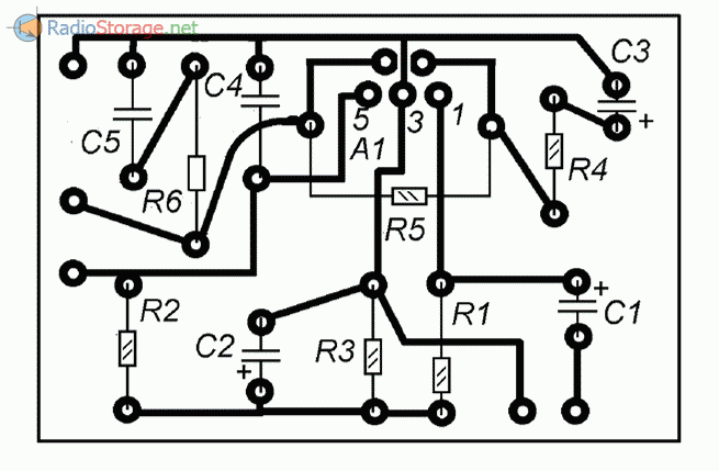
Rice. 2. printed circuit board for the AF power amplifier circuit.
The microcircuits are installed on one common radiator with a surface area of about 400 cm2, which is also an element of the rear wall of the amplifier housing. A ready-made transformer TBS 012 220/24 with a secondary voltage of 24V works in the power supply.
Such a transformer (or similar) can be purchased in shops and bases selling electrical equipment and electrical fittings for the repair and equipment of premises. Usually there is a very wide selection of similar transformers for different voltages and powers.
The body is made of particle board (side panels) and metal plates (top and bottom panels). Front panel, - plexiglass, back, - radiator. Aluminum trays for transporting food are used as blanks for the top and bottom panels.
Chips TDA 2050 can be replaced by domestic counterparts - K174UN30. All electrolytic capacitors must be rated for a voltage of at least 40V (the author used 63V capacitors). The rectifier diodes must allow a forward current of at least 10A. Large capacitors C17-C20, C31, C32 are located directly in the amplifier case.
They are wrapped in Whatman paper and are screwed to the bottom of the case by means of metal clamps. The adjustment consists in adjusting the gains of the amplifiers for A1 and A2, so as to obtain the equality of channels and the necessary sensitivity. For this, the resistances of the resistors R5 and R11 are selected (a decrease in resistance leads to a decrease in sensitivity).
I do not recommend getting too carried away by increasing the sensitivity - first, the THD will increase, and then the amplifier can self-excite. Capacitors C6 and C12 are located near the amplifier boards and are soldered with short conductors to the tracks of these boards. C13, C14, C15 and C16 are located near the rectifier.
The amplifier according to this scheme can be powered from another power source. The maximum supply voltage according to this scheme (unipolar) is 50V while the maximum output power will be about 50W. The minimum supply voltage is only 9V. In this case, the power will be no more than 12W.
Such "wide" supply voltage parameters allow the amplifier to operate from a wide variety of DC sources. It can be a 12V car battery or a 32V power supply from an old HP printer.
In addition, the wide limits of the supply voltage and the ability to change the sensitivity of the amplifier (gain) within a very wide range makes it possible to use it as a repair module to replace a failed ULF of various household audio equipment.


