Current indicator circuit
The first circuit is the simplest current indicator; it can be used in chargers that do not have ammeters. Another design is intended for discrete indication of current, consumed load, operating in an alternating current network. It is indicated by three LEDs, which indicate that the consumed current has exceeded the set switch-on values.
Simple current indicator |
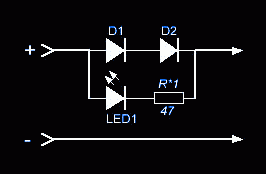
In the role of a current sensor in this device, two diodes connected in the forward direction are used. The voltage drop across them is enough for the LED indicator to light up. A resistance is connected in series with the LED, the rating of which must be selected so that at the maximum values of the load current, the current through the LED does not exceed the permissible value. The maximum forward current of the diodes must be at least twice the maximum load current. Any LED will do.
Mains current LED |
Due to its small dimensions, low electricity consumption and low power loss in the 220V alternating voltage circuit, the radio amateur design can be easily built into a standard household, extension cord, circuit breaker. The indication allows you to track not only the presence of excess current, but also quickly fix the breakdown of the windings of electric motors or an increased mechanical load on the power tool.
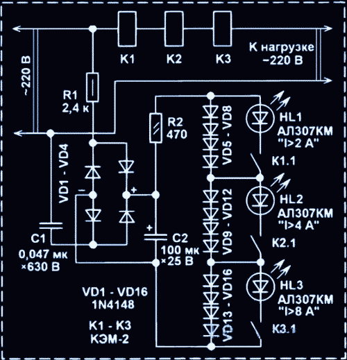
The current sensor is built on self-made reed relays K1 - K3, the windings of which have a different number of turns, therefore, the reed switch contacts are triggered at different ratings of the flowing current. In this circuit, the winding of the first relay has the largest number of turns, therefore, the contacts K1.1 close before the other contacts. With the current consumed by the load from 2 A to 4 A, only the HL1 LED will be on. With closed K1.1, but open contacts of the remaining reed switches, the supply current of the HL1 LED will go through the diode chains VD9 - VD12 and VD13 - VD16. With an increase in the monitored parameter more than 4 A, the contacts of the reed switch K2.1 will start to work and HL2 will also light up. I in a load of more than 8 A.
Since the windings of self-made reed relays have a small number of turns, there is practically no heating of the windings. The LED current indicator unit receives power from a transformerless power supply made on a capacitor C1, current-limiting resistances R1, R2, a VD1-VD4 bridge rectifier. Capacitance C2 smoothes the ripple of the rectified voltage.
The coils of reed switches are made of a winding wire with a diameter of 0.82 mm in one row. In order not to spoil the glass body of the reed switch, it is better to wind the turns of the windings on the smooth part of a steel drill with a diameter of 3.2 mm. The distance between the turns is 0.5 mm. Relay coil K1 - 11 turns, K2 - 6 turns, K3 - only 4 turns. The actuation current of the contacts depends not only on the number of turns, but also on the specific type of reed switch and the location of the coil on the cylinder, when the coil is located in the center of the reed switch body, the sensitivity is the best.
By changing the number of turns of the coils, you can choose other values for indicating the current of the connected loads, at which the LEDs will light up. For a small correction, you can change the position of the coil on the reed switch body. After tuning, the coils are fixed with drops of polymer glue.
4 LED current and power indicator |
The proposed amateur radio design is suitable for light indication of the current consumption (and power) by the load connected to a 220 V alternating network. The device is included in the break of one of the network wires. Design features - no power supply and galvanic isolation. This was achieved by using bright and current transformers.
The current indicator circuit includes a transformer T1, two half-wave rectifiers on VD1 and VD2 with smoothing capacitors C1 and C2. The first rectifier is connected to LEDs HL1 and HL4, to the second - HL2 and HL3. Trimming resistors R1 - R3 are installed in parallel to HL2 - HL4. They can be used to adjust the output current of the rectifier, at which certain LEDs start to light up.
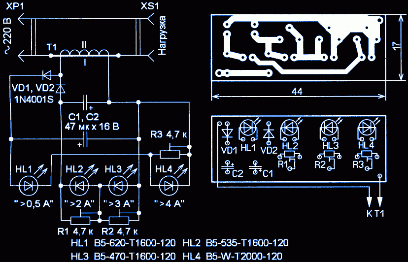
When the load current flows through the primary winding of the current transformer T1, an alternating voltage appears in the secondary, which is rectified by the rectifiers. The indicator is adjusted so that when the load current is below 0.5 A, the voltage at the outputs of the rectifiers is not enough for the LEDs to glow. If the current exceeds this level, a weak, but quite noticeable glow of the HL1 LED (red) will begin. As the load current increases, the rectifier output current also increases. If the load current reaches a level of 2 A, the HL2 LED (green) will light up, with a current higher than 3 A - HL3 (blue), and if the current is more than 4 A, the white HL4 LED will light up. Home experiments have shown that the device is operational up to a current in a load of 12 A, for domestic needs this is quite enough, while the current flowing through the LEDs is no more than 15-18 mA.
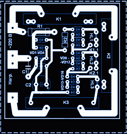
All radio components, except for the current transformer, are mounted on a fiberglass printed circuit board, the drawing of which is shown in the figure above. In the indicator circuit, adjusting resistors SPZ-19 are used, capacities are oxide, diodes can be taken with any low-power rectifier, LEDs - only with increased brightness.
The current transformer is made by hand from a step-down transformer of a small-sized power supply (120/12 V, 200 mA). The active resistance of the primary winding is 200 ohms. The transformer windings are wound in different sections. For the above circuit parameters, the number of turns of the primary winding of the transformer is three, the wire must be in good insulation and designed for the mains voltage and current consumed by the load. For the manufacture of a transformer, you can take any low-power serial step-down transformer, for example, TP-121, TP-112.
To calibrate the scale, you can use an alternating current ammeter and a step-down transformer with a secondary voltage of 5-6 V and a current of up to a couple of amperes. By changing the rating of the load resistance, the required current is set and the trimming resistors achieve the ignition of the corresponding LED.
Correct operation of a car battery is a guarantee of a long service life and safe operation. Monitoring the charging-discharging mode of the battery makes it possible to take measures in time, as well as monitor the correct operation of the generator, starter and car wiring.
The indicator monitors the voltage drop on the conductor connecting the negative terminal of the battery with the "Mass" of the car. This conductor is connected to the classic resistive measuring bridge R1-R5, which makes it possible to remove bipolar signals from it and amplify them using an operational amplifier with a unipolar supply. Diodes VD1-VD4 are connected to the negative feedback circuit of the op-amp DA1, which expand the limits of the measured current, making it possible to measure even the current consumption by the starter when starting the car engine.
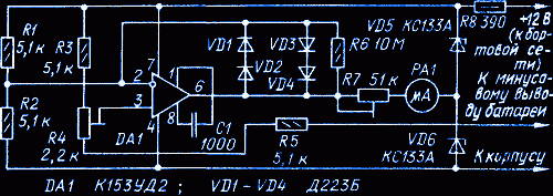
The recording instrument is any magnetoelectric milliammeter with a scale with a zero in the middle, for example M733 with a total deflection current of the needle of 50 μA. On the scale, it is most convenient to evenly arrange three marks to the right and left of zero: 5 A, 50 A and 500 A. The indicator is powered by a 6.6 V parametric voltage regulator. The right terminal of resistance R5 is left permanently connected to the negative terminal of the battery.
To calibrate the scale, first, power is supplied directly from the battery and the trimmer resistance R4 is used to set the microammeter needle to zero. Then, with the ignition key off, we connect the positive terminal of the battery through a powerful (about 60 W) resistance of 2.4 ohms connected to the car body and the trimmer resistance R7, set the ammeter arrow to 5 A. After calibration, the positive terminal of the indicator power supply is connected to the positive terminal of the on-board network car.


