All electronics engineers involved in the design of power supply devices, sooner or later, are faced with the problem of the lack of a load equivalent or functional limitations of the existing loads, as well as their dimensions. Fortunately, the appearance on the Russian market of cheap and powerful field-effect transistors has somewhat corrected the situation.
Amateur designs of electronic loads based on field-effect transistors began to appear, which are more suitable for use as electronic resistance than their bipolar counterparts: better temperature stability, almost zero channel resistance in the open state, low control currents - the main advantages that determine the preference of their use as regulating component in powerful devices. Moreover, a wide variety of offers appeared from manufacturers of devices, whose prices are full of a wide variety of models of electronic loads. But, since manufacturers focus their highly complex and multifunctional products called "electronic load" mainly on production, the prices for these products are so high that only a very wealthy person can afford to buy. True, it is not entirely clear why a wealthy person needs an electronic load.
I didn’t notice an industrial manufacture oriented to the amateur engineering sector. So, again, you have to do everything yourself. Eh ... Let's start.
Benefits of electronic dummy load
Why, in principle, electronic load equivalents are preferable to traditional means (powerful resistors, incandescent lamps, thermal heaters and other devices), which are often used by designers when setting up various power devices?
Citizens of the portal related to the design and repair of power supplies undoubtedly know the answer to this question. Personally, I see two factors sufficient to have an electronic load in my "laboratory": small dimensions, the ability to control the load power within a large range by simple means (as we adjust the sound volume or the output voltage of the power supply - with an ordinary variable resistor and not by the powerful contacts of the switch, the rheostat engine, etc.).
In addition, the "actions" of an electronic load can be easily automated, thus making it easier and more sophisticated to test a power device with an electronic load. This, of course, frees the eyes and hands of the engineer, and the work becomes more productive. But about the delights of all possible bells and whistles and perfection - not in this article, and, perhaps, from another author. In the meantime, - just about another type of electronic load - impulse.
Features of the impulse version of the EN
Analog electronic loads are certainly good, and many of those who have used EN when setting up power devices have appreciated its advantages. Pulse EHs have their own flavor, making it possible to evaluate the operation of the power supply with a pulsed nature of the load, such as, for example, the operation of digital devices. Powerful amplifiers of audio frequencies also have a characteristic effect on power supplies, and therefore, it would be nice to know how a power supply, designed and manufactured for a specific amplifier, will behave under a certain given nature of the load.
When diagnosing repaired power supplies, the effect of using a pulsed EN is also noticeable. So, for example, with the help of a pulsed EN, a malfunction of a modern computer power supply was found. The declared malfunction of this 850-watt power supply unit was as follows: when working with this power supply unit, the computer turned off arbitrarily at any time when working with any application, regardless of the power consumed at the time of shutdown. When tested for a normal load (a bunch of powerful + 3V, + 5V resistors and + 12V halogen bulbs), this PSU worked with a bang for several hours, despite the fact that the load power was 2/3 of its declared power. The malfunction manifested itself when the impulse EN was connected to the + 3V channel and the power supply unit began to turn off, as soon as the ammeter arrow reached division 1A. In this case, the load currents for each of the other positive voltage channels did not exceed 3A. The supervisor's board turned out to be faulty and was replaced with a similar one (fortunately, there was the same power supply unit with a burnt out power unit), after which the power supply unit worked normally at the maximum current allowed for the used copy of the pulsed EN (10A), which is the subject of description in this article.
Idea
The idea of creating a pulsed load appeared a long time ago and was first implemented in 2002, but not in its current form and on a different element base and for somewhat different purposes, and at that time there was no sufficient incentive for me personally to develop this idea. Now the stars are different and something has come together for the next embodiment of this device. On the other hand, the device originally had a slightly different purpose - checking the parameters of pulse transformers and chokes. But one does not interfere with the other. By the way, if anyone would like to study inductive components using this or a similar device, please: below are the archives of articles by venerable (in the field of power electronics) engineers devoted to this topic.
So, what is the "classical" (analog) EN in principle? Current stabilizer operating in short circuit mode. And nothing more. And it will be right whoever, in a fit of any kind of passion, closes the output terminals of the charger or welding machine and says: this is an electronic load! It is not a fact, of course, that such a short circuit will not have detrimental consequences, both for the devices and for the operator himself, but both devices are indeed current sources and could well claim, after some refinement, to the role of an electronic load, like any another arbitrarily primitive current source. The current in the analog EN will depend on the voltage at the output of the tested power supply unit, the ohmic resistance of the field-effect transistor channel, set by the voltage at its gate.
The current in a pulsed EN will depend on the sum of parameters, which will include the pulse width, the minimum resistance of the open channel of the output switch and the properties of the tested power supply unit (capacitance of capacitors, inductance of power supply chokes, output voltage).
With an open key, the EN forms a short-term short circuit, in which the capacitors of the power supply under test are discharged, and the chokes (if they are contained in the power supply structure) tend to saturation. The classical short circuit, however, does not occur, since the pulse width is limited in time by microsecond values that determine the value of the discharge current of the power supply capacitors.
At the same time, checking the impulse EN is more extreme for the tested power supply. On the other hand, such a check reveals more "pitfalls", up to the quality of the supply conductors supplied to the supply device. So, when a pulsed EH was connected to a 12-volt power supply unit with connecting copper wires with a core diameter of 0.8 mm and a load current of 5A, the oscillogram on the EH revealed pulsations, which were a sequence of rectangular pulses with a swing of up to 2V and spiky surges with an amplitude equal to the supply voltage. At the terminals of the power supply unit itself, there were practically no pulsations from the EN. At the EN itself, ripples were minimized (less than 50 mV) by increasing the number of cores of each conductor supplying the EN itself - up to 6. In the "two-core" version, the minimum ripple, comparable to the "six-core", was achieved by installing an additional electrolytic capacitor with a capacity of 4700 mF at the connection points supply wires with load. So, when building a power supply, a pulsed EN can be very useful.
Scheme
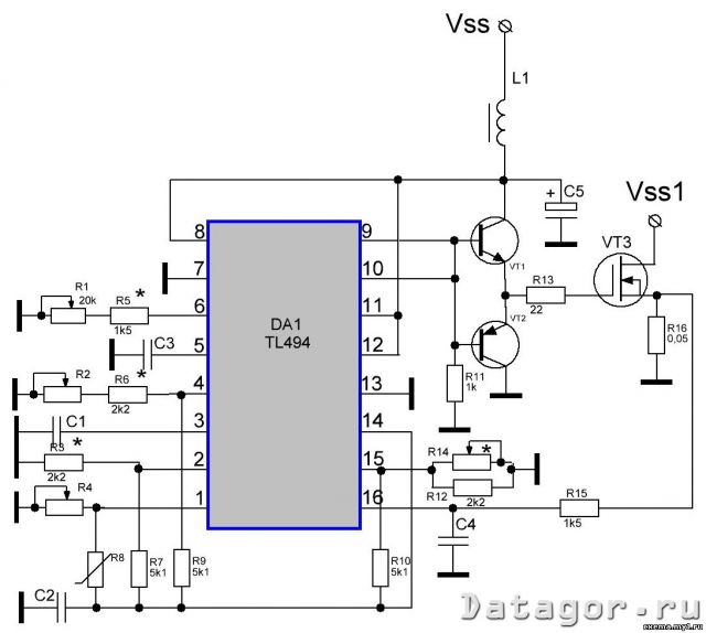
EN is assembled on popular (due to the large number of recycled computer power supplies) components. The EN circuit contains a generator with an adjustable frequency and pulse width, thermal and current protection. The generator is made on PWM TL494.
The frequency is controlled by a variable resistor R1; duty cycle - R2; thermal sensitivity - R4; current limitation - R14.
The generator output is powered by an emitter follower (VT1, VT2) to operate on the capacitance of the gates of field-effect transistors from 4 or more.
The generator part of the circuit and the buffer stage on transistors VT1, VT2 can be powered from a separate power source with an output voltage of +12 ... 15V and a current of up to 2A or from the + 12V channel of the tested power supply.
The output of the EN (drain of the field-effect transistor) is connected to the "+" of the tested power supply unit, the common wire of the EN is connected to the common wire of the power supply unit. Each of the gates of field-effect transistors (in the case of their group use) must be connected to the output of the buffer stage with its own resistor, leveling the difference in gate parameters (capacitance, threshold voltage) and ensuring the synchronous operation of the switches.
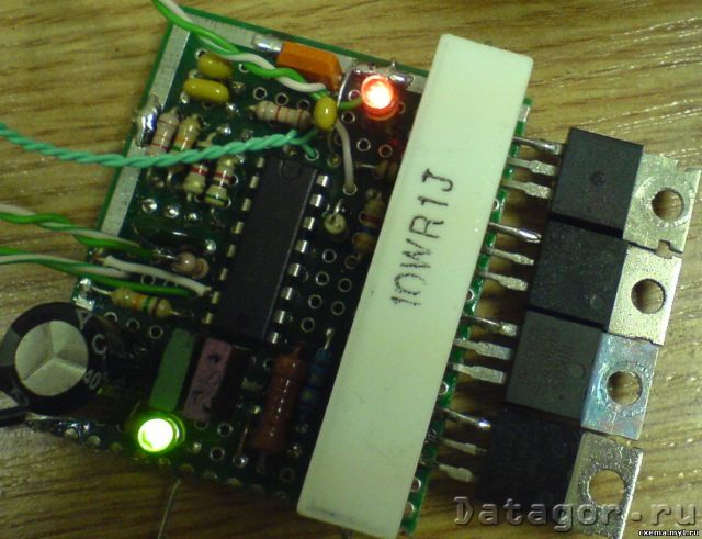
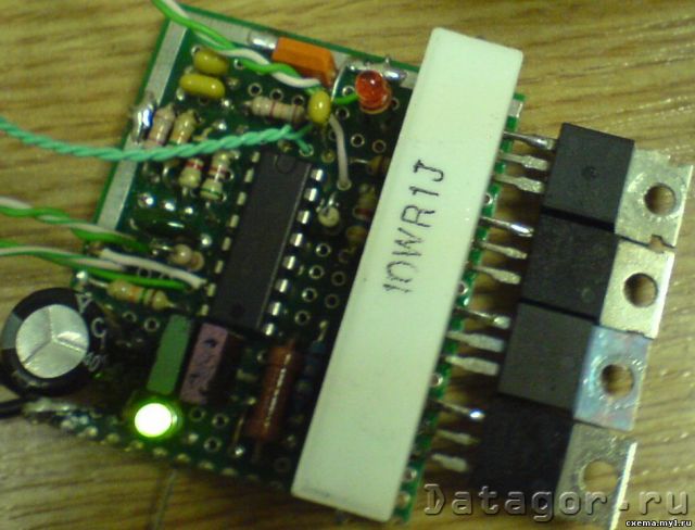
The photographs show that there is a pair of LEDs on the EN board: green is the load power indicator, red indicates the operation of the microcircuit error amplifiers at a critical temperature (constant glow) or when the current is limited (barely noticeable flickering). The operation of the red LED is controlled by a key on the KT315 transistor, the emitter of which is connected to the common wire; base (through a 5-15kOhm resistor) with pin 3 of the microcircuit; collector - (through a 1.1 kOhm resistor) with the cathode of the LED, the anode of which is connected to pins 8, 11, 12 of the DA1 microcircuit. This node is not shown in the diagram, because is not absolutely required.
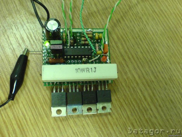
Regarding the resistor R16. When a current of 10A passes through it, the power dissipated on the resistor will be 5W (at the resistance indicated in the diagram). In a real design, a 0.1 ohm resistor is used (the required rating was not found) and the power dissipated on its case at the same current will be 10W. The temperature of the resistor is much higher than the temperature of the EN keys, which (when using the radiator shown in the photo) do not heat up very much. Therefore, it is better to install the thermal sensor on the R16 resistor (or in the immediate vicinity), and not on the radiator with EN keys.
ARCHIVE:


