When I found on Ebay a tiny amplifier "PAM8610 stereo mini class D digital power amplifier board 2 x15W", measuring 2.5 * 3 cm and costing about 350 rubles, I realized that I just could not pass by.
It turned out that 2 * 15W is the only option for 4 ohm speakers. I did not have such, so I connected 2 * 10W with an indicator of 6 ohms.
Class D amplifiers have received a lot of negative reviews from "serious" music lovers, but everything sounded just great (and loud!) To my ears, especially with decent speakers and an MP3 player with a built-in graphic equalizer and various additional settings.
The use of an mp3 player also means that there is no need to control the lows, highs and mids through a homemade sound amplifier, it only needs a volume control.
Due to the fact that the wiring between the components is very simple, even novice amateurs can easily assemble this project with their own hands.
Step 1: Assemble the required components
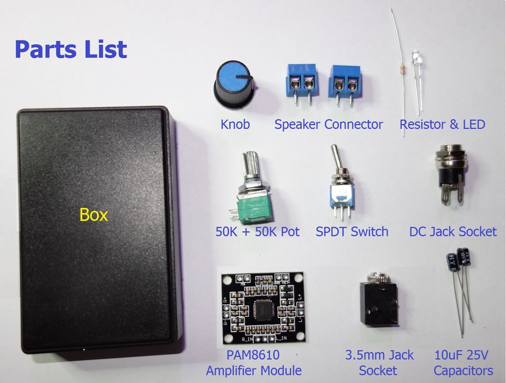
To create an amplifier, we need:
- 1pc * Plastic box. Mine was about 8 * 5 * 2.2 cm
- 1pc * PAM8610 Digital Power Amplifier Board 2 x 15w
- 1pc * 50K + 50K Dual Potentiometer
- 1pc * Double Potentiometer Button - Match the color to your liking.
- 1pc * Single Pole, Double Throw Switch (SPDT, Single Pole - Double Throw)
- 1 pc * 3.5 mm stereo jack socket for installation on the case
- 1 pc * Power jack socket for installation on the case
- 2 pcs * 10uF 25V electrolytic capacitors - the smaller the better
- 2 pcs * 2-terminal or 1 pcs * 4-terminal blocking screw terminals
- 1pc * 3mm LED (any color you like)
- 1pc * 4.7K 1 / 8W resistor (LED current limiting - see app for more details)
- 1pc * 12V 2A AC adapter (more details in the app)
- 1pc * diode 1N5401 or 1N5822 (optional)
In addition, to connect the components, you will need a multi-colored stranded (7-core) wire.
I have attached a PDF with a very detailed explanation of each component on the list. I wrote this document primarily for beginners, so if you only want a list of components, skip most of the document and read only about the AC Adapter - this is very important.
Files
Step 2: Necessary tools
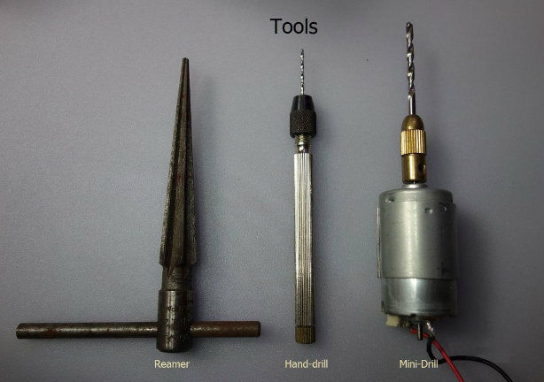
This project has kept the amount of mechanical work to a minimum, so you only need three basic tools. Tools are needed for drilling holes and soldering:
- Hand drill with 1 mm bit for drilling holes.
- Large drill for enlarging holes.
- Expander drill.
- Soldering iron 18W - 25W.
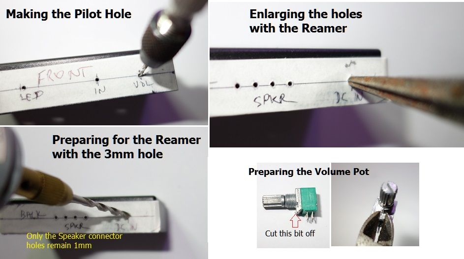
The reaming drill is my favorite tool for punching holes in plastic and metal, and I recommend that everyone keep it in their toolbox at all times. After making a 3 mm hole in the center of the platform, on which the desired component will be located, you take the drill and slowly press it in, turning it clockwise. After every few turns, you check that the component fits and sits firmly in the hole.
Soldering iron. Nothing new can be said about this tool that has not already been described in hundreds of other articles. All you need to know is that practice is the key to excellence. You will be working with a printed circuit board that has chips on its surface, so be very careful. Avoid splashing solder - one drop can ruin the entire amplifier.
Step 3: preparing the case
In this step, we will prepare the box for installing all the necessary components into it.
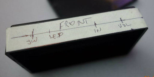
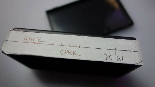
Apply a clean white tape to the surface of the chassis where you intend to install the switches and controls. In my case, I decided to make the front and rear panels, as is the case with real amplifiers, and noted where each component will be located (see photo).
The sticker allows you to mark the location of all control components and at the same time protects the surface of the case from scratches while you are drilling holes, etc.
Using a 1mm mini drill, drill the pilot holes using the marks you made earlier. Then expand the holes with a 3mm drill (excluding the holes for the speaker connectors). Then expand the holes with a drill (following the prompts from the previous part of the instructions). Do not expand the LED hole by 3mm unless you intend to use a larger diameter diode.
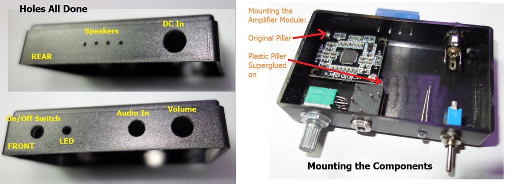
You can see the results of the work in the attached photos - neat holes that do not require further processing.
You may notice that all of the components are already screwed to the case, except for the speaker terminals, they are threaded through 1mm holes and super-glued to the case. The LED just fits snugly in the hole, but it can be additionally secured with superglue.
Step 4: connecting the components
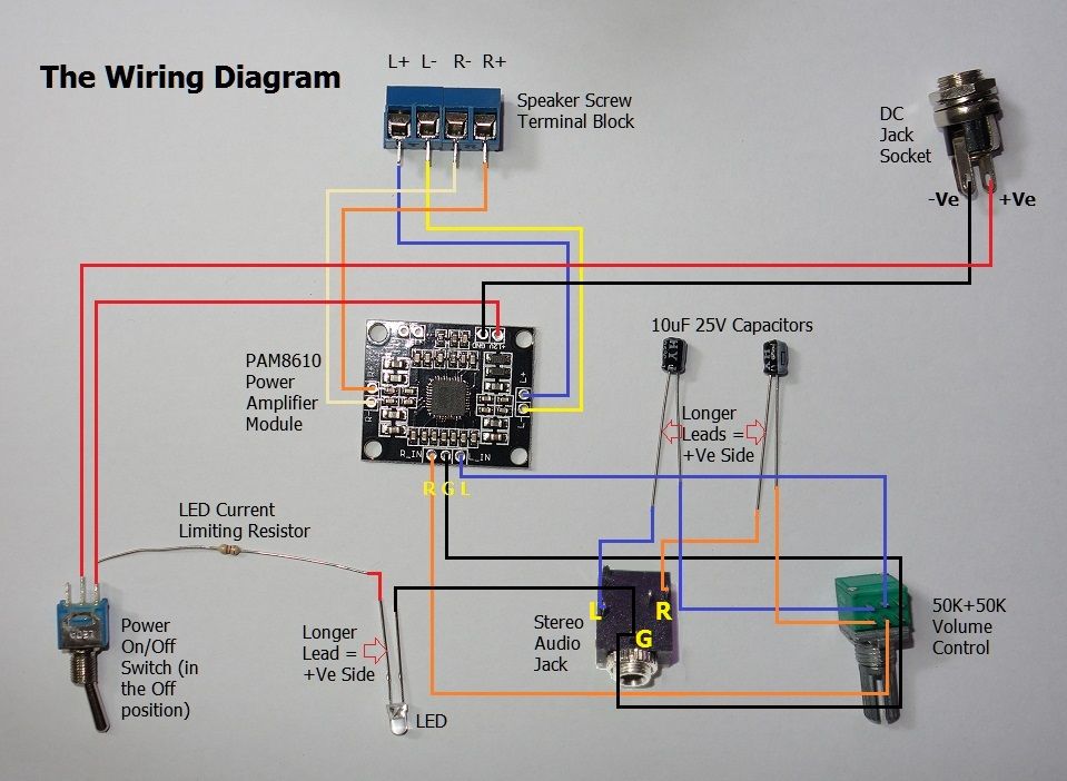
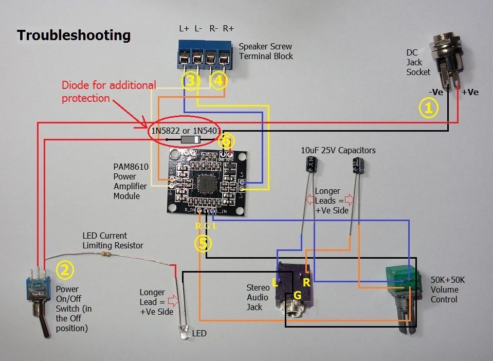
The wiring is very simple. For easy debugging, if something suddenly doesn't work, I recommend using wires of different colors. For example, red for positive wires, black for negative or ground wires, orange for all right channels, and blue for left channels. To connect the speakers, I used orange for right +, white for right -, blue for left +, brown for left -. You can use your own color combination, but try to use the same colors for the left and right channels.
There are just a couple of simple things you need to know about polarity, read the attached PDF to familiarize yourself with this information.
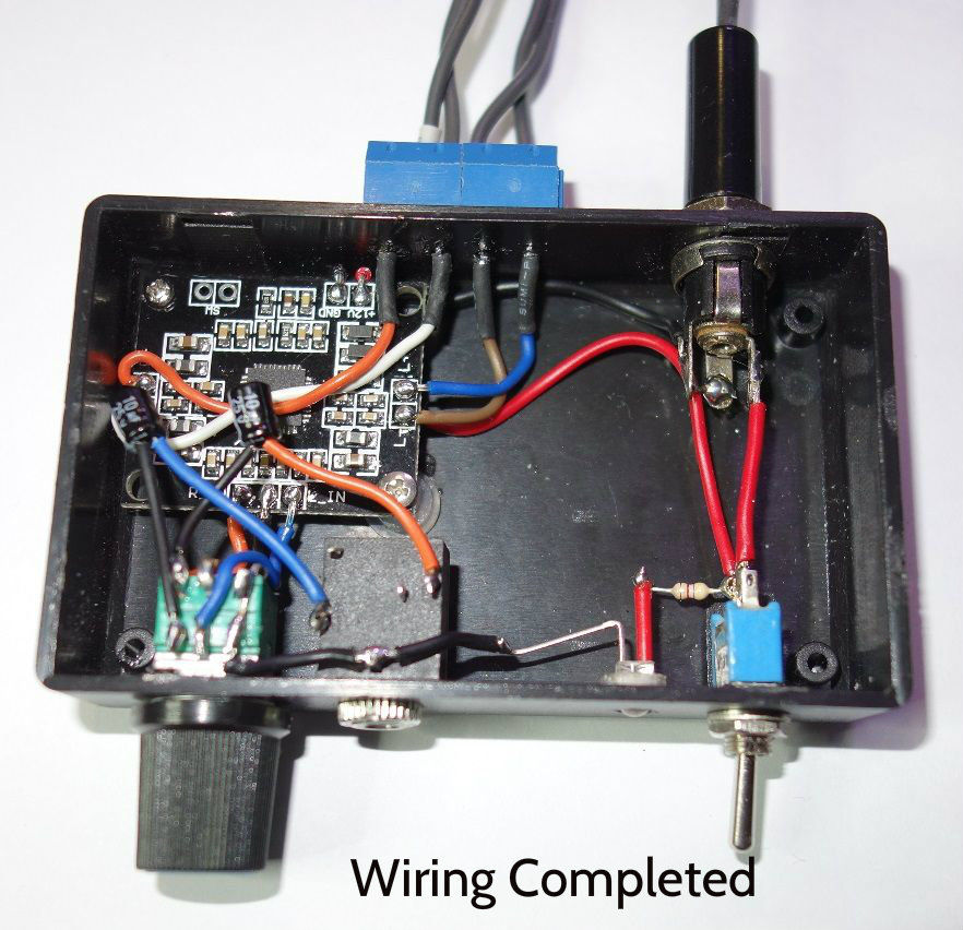
Also take into account that I am installing everything in a box using it as the top of my amp with the box lid on the bottom. This means that I am working with a mirrored build diagram. In real life, all components installed on the left will be on the right and vice versa. Be careful when connecting the speaker wires, if your layout is the same as mine, the left speaker connections will be on the right and the right speaker connections will be on the left. This way, when you flip the amp case, everything will fall into place.
By looking at the attached photo, you can see how easy it is to connect.
Files
Step 5: Troubleshooting and Precautions after Assembly
After you have soldered everything and before you connect the speakers and turn on the amplifier, you need to do some preliminary tests.
Recheck the correct connection of the components, or rather entrust it to your friend, and make sure that everything is connected correctly. Taking a fresh look at the project will help you see things that you won't notice after hours at home working.
Using a multimeter, on small resistance ranges, check the circuit for a short at points 1, 3, 4, 5 and 6:
- If you have a short at point 1, then your power adapter will explode as soon as you plug it into an outlet.
- If you have a short between the speaker pins, or between any of the pins on points 3 or 4 and ground, then your amplifier module will explode. The right and left minuses are not common points, so under no circumstances short them together or connect them to ground.
- If there is a short circuit between the left or right channel and ground at point 5, then one of the channels may not work when turned on.
- If the short is at point 6, then your power adapter will explode as soon as you turn on the switch on the case.
Regarding the power switch (point 2), if you expect it to be on in the Down position and off in the Up position, set the switch to the Down position and using your Ohm multimeter, measure the resistance between the two points soldering. If you receive anything other than zero ohms, then the switch is flipped. Loosen the mounting screw and flip the switch 180 degrees until it is in the up position. Shift it down and check the resistance again. If it is still nonzero, then your switch is most likely faulty.
Additional protection. As noted earlier, you can damage the AC adapter by using the opposite polarity of your amplifier's wiring. You can be safe by adding one diode in series to the positive connection of the board. The connection diagram is shown in the attached diagram.
In this case, if you connect the adapter with reverse polarity and turn on the device, the diode will prevent the voltage from reaching the amplifier module. In this case, the LED will also not light up - this will be an indicator for you that the polarity of the adapter is incorrect or the adapter itself is defective.
The only drawback of such protection is that after the current passes through the diode, there will be a slight drop in voltage, which is very important if your adapter outputs exactly 12V.
I recommend taking both 3A diodes. The difference is the forward voltage drop. If you are using a standard 1N5401 rectifier, the voltage drop is about 0.7V, so the available voltage is 11.3V or less. When using the Schottky Barrier Rectifier 1N5822, the drop is only 0.4V at 2A, so you will have at least 11.7V (which is closer to 12V). Choose one of these diodes based on your needs. For example, if the output voltage of your AC adapter is 13V (which is quite possible), then the 0.7V drop shouldn't matter, so you can use the 1N5401.
MAXIMUM VOLTAGE OF THE DEVICE: The maximum voltage that the amplifier module can handle is 16V. To avoid damaging it, check the actual output voltage of your AC adapter with a multimeter before connecting and make sure it is well below 16V.
Step 6: Turn on the device
Once you have checked that everything is soldered well and that there are no short circuits in the circuit (and also soldered the recommended diodes), you can connect the AC adapter, speakers (thread the entire bare section of the wire to the end so that the insulation reaches the terminal) and the mp3 player, slightly raise volume level and turn on music. Enjoy the sound.
If you haven't used a diode for protection, then there is one more precaution you can take before turning on the power. Keep the + 12V wire that goes to the amplifier module disconnected, connect the AC adapter, turn on the power and use a multimeter in the DC range, connect its red end to the disconnected red wire, and the black end to any black connection (ground), check that voltage reading is positive in the range of about 12V.
Once you are sure that the voltage and polarity are correct, turn off the device, unplug the adapter, solder the red + 12V wire to the amplifier module and turn everything on following the instructions above. You are already on your way to sound good!
Step 7: Conclusions
At the beginning of the work on the instructions, I wanted to make everything simple and fast, so that every beginner would understand how easy it is to create an inexpensive and small stereo amplifier. As the article was written, more and more nuances appeared that I would like to describe in more detail. Instead of embedding it all in the body text, I made a couple of PDFs and attached them to the steps I needed. I hope I haven't crossed the line between informativeness and boredom.
If you are new to electronics and you are going to create your own amplifier, then you should have at least basic tools such as a soldering iron, solder, multimeter, screwdriver, pliers and wire cutters. Also, please read all attached PDF files before starting.
A lot of information is based on my many years of experience in the home appliance repair business as well as training technicians for these tasks. It was very difficult for me not to mention all the nuances described, and especially due to the fact that most authors do not delve into these problems. For me, it's the difference between success or failure of a project.
Hope you enjoy everything!


