If you have an old computer power supply (ATX) at home, then you should not throw it away. After all, it can be used to make an excellent power supply for home or laboratory purposes. The refinement will be minimal and in the end you will get an almost universal power supply with a number of fixed voltages.
Computer power supplies have a large load capacity, high stabilization and short circuit protection.
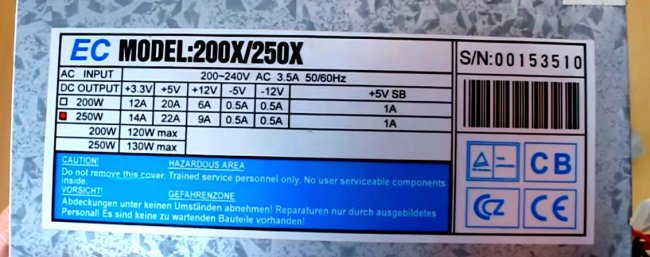
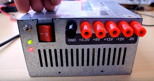
I took this block. Everyone has such a plate with a number of output voltages and the maximum load current. Basic voltages for continuous operation 3.3 V; 5 V; 12 V. There are also outputs that can be used for a small current, these are minus 5 V and minus 12 V. You can also get a voltage difference: for example, if you connect to “+5” and “+12”, then you get a voltage of 7 V. If you connect to "+3.3" and "+5", you will get 1.7 V. And so on ... So the voltage line is much larger than it might seem at once.
Pinout of computer power supply outputs
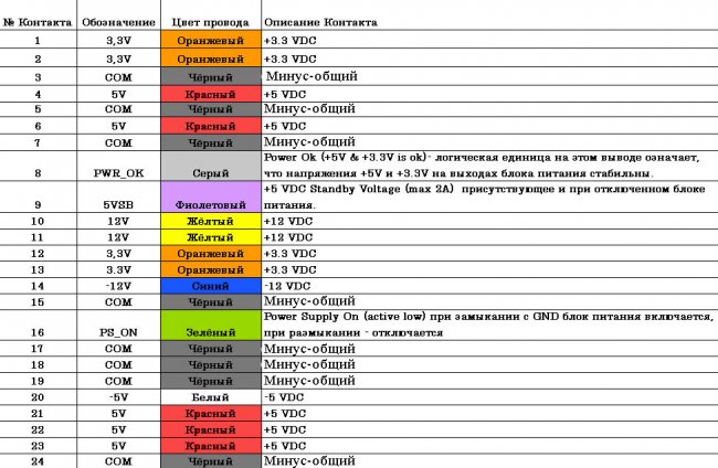
The color standard is basically the same. And this color scheme is 99 percent right for you. Something may be added or removed, but of course everything is not critical.
Rework has begun
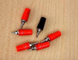
What do we need?- - Screw terminals.
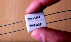
- - Resistors with a power of 10 W and a resistance of 10 ohms (you can try 20 ohms). We will use composite of two five-watt resistors.
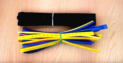
- - Heat shrink tubing.
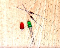
- - A pair of LEDs with 330 ohm damping resistors.
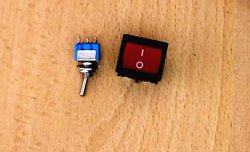
- - Switches. One for network, one for control
Scheme for finalizing the computer power supply
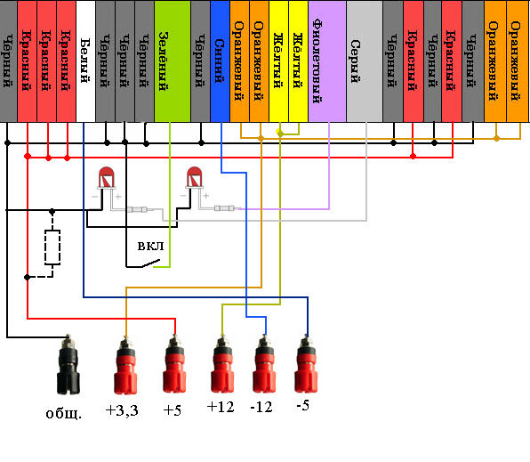
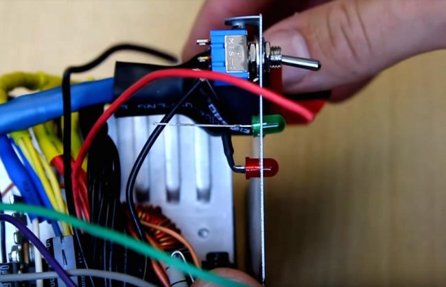
It's simple, so don't be afraid. The first thing to do is to disassemble and connect the wires by color. Then, according to the diagram, connect the LEDs. The first one on the left will indicate the presence of power at the output after switching on. And the second one on the right will always burn as long as the mains voltage is present on the unit.
Connect switch. It will start the main circuit by shorting the green wire to common. And turn off the unit when opened.
Also, depending on the brand of the unit, you will need to hang a 5-20 ohm load resistor between the common output and plus five volts, otherwise the unit may not start due to the built-in protection. Also, if it doesn’t work, be prepared to hang such resistors for all voltages: “+3.3”, “+12”. But usually one resistor is enough for a 5 volt output.
Let's start
Remove the top cover of the casing.We bite off the power connectors going to the computer motherboard and other devices.
We unravel the wires by color.
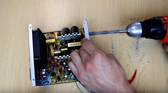
We drill holes in the back wall for the terminals. For accuracy, we first pass with a thin drill, and then with a thick one to fit the size of the terminal.
Be careful not to sprinkle metal shavings on the power supply board.
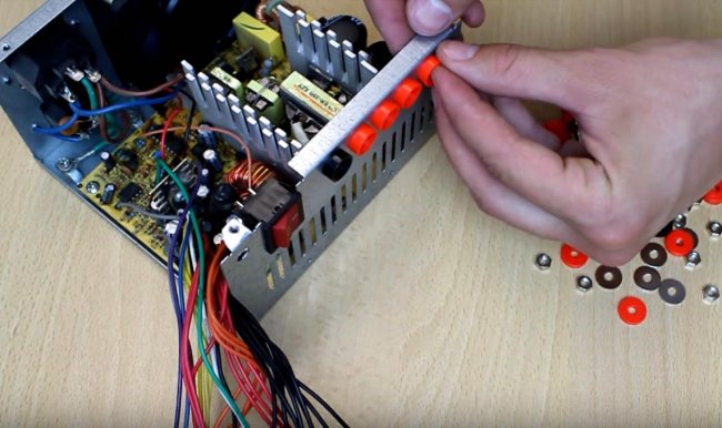
Insert the clamps and tighten.
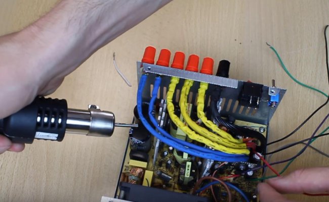
We add black wires, it will be common, and we clean it. Then we tin with a soldering iron, put on a heat shrink tube. We solder to the terminal and put the tube on the solder - we blow it with a hot air gun.
We do this with all wires. Which you do not plan to use - bite off at the root of the board.
We also drill holes for the toggle switch and LEDs.
We install and fix the LEDs with hot glue. We solder according to the scheme.
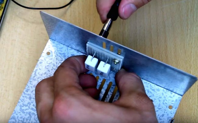
We put the load resistors on the circuit board and screw them on.
We close the lid. We turn on and check your new laboratory power supply.
It will not be superfluous to measure the output voltage at the output of each terminal. To be sure that your old power supply is fully functional and the output voltages are not out of range.
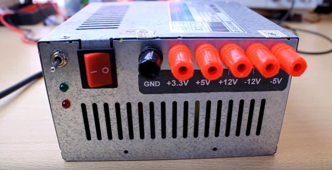
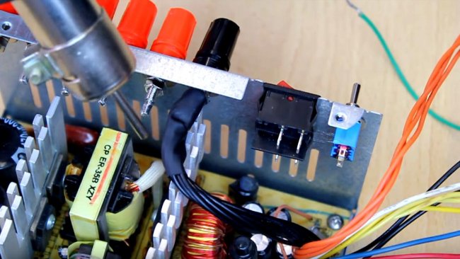
As you can see, I used two switches - one is in the circuit, and it starts the block. And the second, which is larger, bipolar - switches the input voltage of 220 V to the input of the unit. You can not put it.
So friends, collect your block and use it to your health.