Recently, a certain person approached with a request to assemble an amplifier of sufficient power and separate amplification channels for low, medium and high frequencies. before that, I had already collected for myself more than once as an experiment and, I must say, the experiments were very successful. The sound quality of even inexpensive speakers of a not very high level is noticeably improved in comparison, for example, with the option of using passive filters in the speakers themselves. In addition, it becomes possible to quite easily change the frequency of the division of the bands and the gain of each individual band and, thus, it is easier to achieve a uniform frequency response of the entire sound reinforcement path. In the amplifier, ready-made circuits were used, which had previously been tried out more than once in simpler designs.
Structural scheme
The figure below shows the circuit for channel 1:
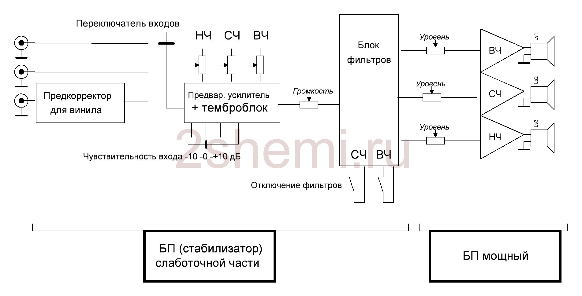
As you can see from the diagram, the amplifier has three inputs, one of which provides for the simple possibility of adding a preamplifier-equalizer for a vinyl player (if necessary), an input switch, a preamplifier-timbre (also three-band, with adjustable HF / MF / LF levels), a volume control, a three-band filter unit with adjustable gain for each band with the ability to turn off filtering and a power supply for high-power final amplifiers (unstabilized) and a stabilizer for the "low-current" part (preliminary amplification stages).
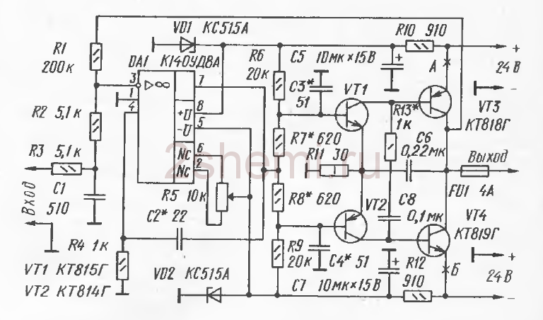
Pre-amplifier-timbre block
As it, a scheme was used, which had been tested more than once before, which, with its simplicity and availability of parts, shows fairly good characteristics. The scheme (like all subsequent ones) was at one time published in the magazine "Radio" and then more than once published on various sites on the Internet:
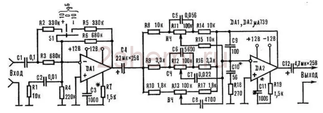
The input stage on DA1 contains a gain level switch (-10; 0; +10 dB), which simplifies matching the entire amplifier with signal sources of different levels, and a tone control is directly assembled on DA2. The circuit is not capricious to a certain range of element ratings and does not require any adjustment. As an op-amp, you can use any microcircuits used in the sound paths of amplifiers, for example, here (and in subsequent circuits) I tried imported BA4558, TL072 and LM2904. Anything will do, but it is better, of course, to choose op-amp options with the lowest possible noise level and high speed (input voltage slew rate). These parameters can be found in reference books (datasheets). Of course, here it is not at all necessary to use this particular scheme, it is quite possible, for example, to make not a three-band, but a regular (standard) two-band tone block. But not a "passive" circuit, but with stages of amplification-matching at the input and output on transistors or op-amp.
Filter block
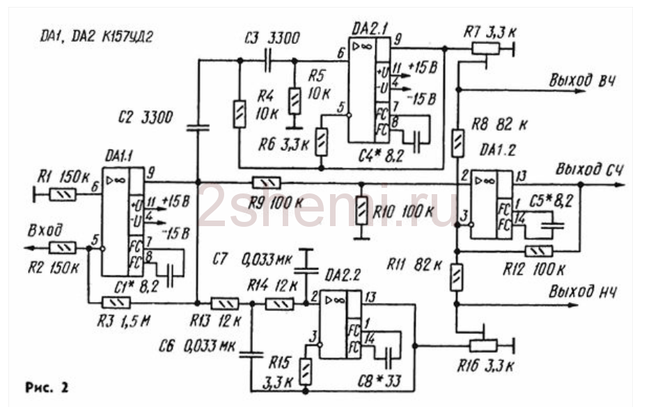
You can also find a lot of filter circuits, if you wish, since there are now enough publications on the topic of multiband amplifiers. To facilitate this task and just for example, I will present here several possible schemes found in various sources:
- the circuit that was applied by me in this amplifier, since the frequencies of the crossover were exactly the ones that the "customer" needed - 500 Hz and 5 kHz, and there was no need to recalculate anything.
- the second scheme, simpler on the op-amp.
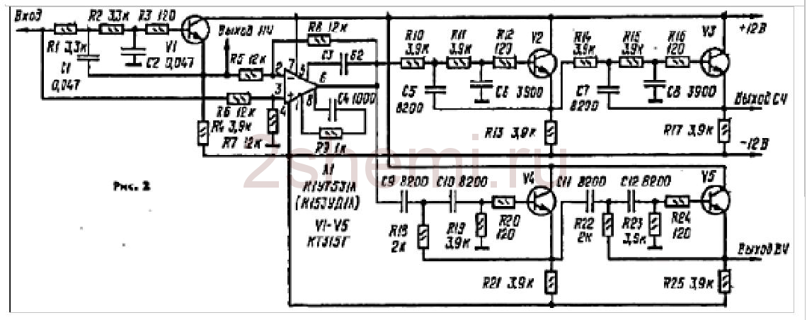
And one more possible circuit, on transistors:
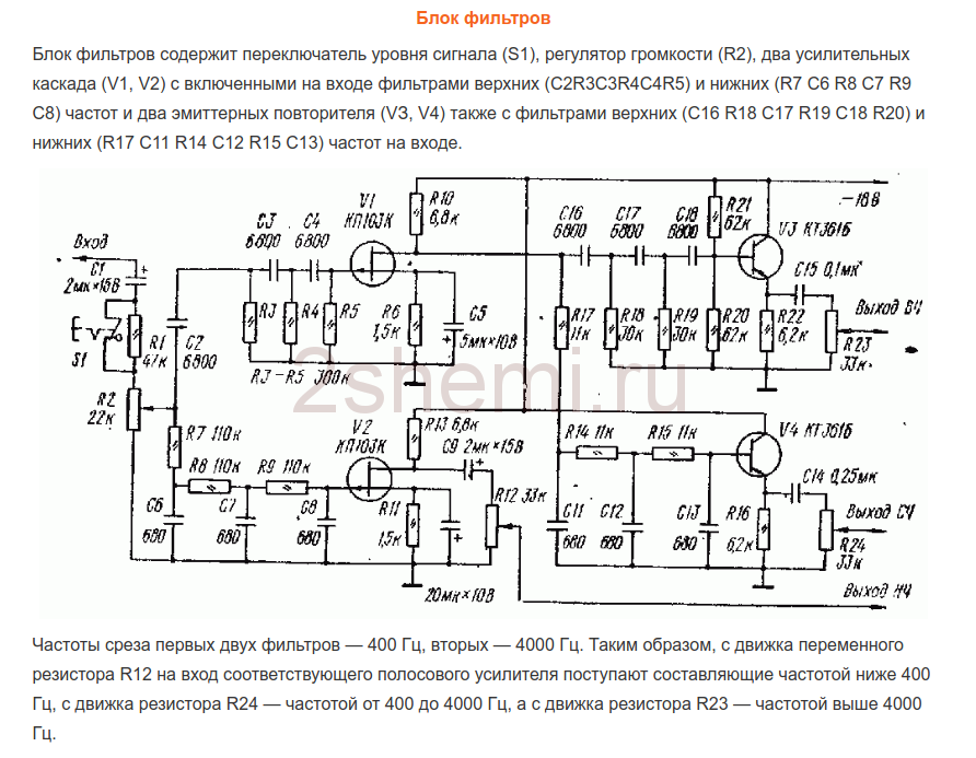
As yours already wrote, I chose the first scheme because of the rather high-quality filtering of the bands and the correspondence of the band separation frequencies to the given ones. Only at the outputs of each channel (strip) were simple gain controls added (as is done, for example, in the third circuit, on transistors). Regulators can be supplied from 30 to 100 kOhm. Operational amplifiers and transistors in all circuits can be replaced with modern imported ones (taking into account the pinout!) To obtain the best circuit parameters. All these circuits do not require any tuning, if you do not need to change the frequency of the crossover. Unfortunately, I am not able to give information on recalculating these frequencies of the section, since the circuits were searched for "ready-made" examples and detailed descriptions were not attached to them.
In the filter block circuit (the first of the three), the ability to turn off filtering on the MF and HF channels was added. For this, two push-button switches of the P2K type were installed, with the help of which you can simply close the connection points of the filter inputs - R10C9 with their corresponding outputs - "high-frequency output" and "mid-frequency output". In this case, a complete audio signal is sent through these channels.
Power amplifiers
From the output of each channel of the filter, the HF-MF-LF signals are fed to the inputs of the power amplifiers, which can also be assembled according to any of the known schemes, depending on the required power of the entire amplifier. I made UMZCH according to the well-known scheme from the magazine "Radio", No. 3, 1991, p. 51. Here I give a link to the "primary source", since about this scheme there are many opinions and disputes on the grounds of its "quality". The fact is that at first glance this is a class B amplifier circuit with the inevitable presence of crossover distortion, but this is not the case. The circuit uses current control of the output stage transistors, which makes it possible to get rid of these drawbacks with a normal, standard connection. At the same time, the circuit is very simple, not critical to the parts used, and even transistors do not require special preliminary selection in terms of parameters. In addition, the circuit is convenient in that powerful output transistors can be installed on one heat sink in pairs without insulating gaskets, since the collector leads are connected at the point " output ”, which greatly simplifies the installation of the amplifier:
When setting up, it is only IMPORTANT to select the correct operating modes for the transistors of the pre-terminal stage (by selecting resistors R7R8) - on the bases of these transistors in the "rest" mode and without load at the output (speaker) there should be a voltage within 0.4-0.6 volts. The supply voltage for such amplifiers (there should be 6 of them, respectively) was raised to 32 volts with the replacement of the output transistors with 2SA1943 and 2SC5200, the resistance of the resistors R10R12 should also be increased to 1.5 kΩ (to "make life easier" for the zener diodes in the circuit power supply of the input op-amps). The op amps were also replaced by VA4558, thus the "zero setting" circuit is no longer needed (outputs 2 and 6 in the diagram) and, accordingly, the pinout changes when soldering the microcircuit. As a result, during testing, each amplifier according to this scheme gave out power up to 150 watts (for a short time) with a completely adequate degree of heating of the radiator.
ULF power supply
Two transformers with rectifier and filter units according to the usual standard scheme were used as a power supply unit. To power the low-frequency band channels (left and right channels) - a 250-watt transformer, a rectifier on diode assemblies such as MBR2560 or similar, and capacitors 40,000 microfarads x 50 volts in each power arm. For MF and HF channels - a 350-watt transformer (taken from a burnt-out Yamaha receiver), a rectifier - a TS6P06G diode assembly and a filter - two capacitors of 25,000 microfarads x 63 volts for each power arm. All electrolytic capacitors of the filters are shunted with film capacitors with a capacity of 1 μF x 63 volts.
In general, the power supply can be with one transformer, of course, but with its corresponding power. The power of the amplifier as a whole in this case is determined solely by the capabilities of the power source. All preamplifiers (tone block, filters) are also powered from one of these transformers (it is possible from any of them), but through an additional block of a bipolar stabilizer assembled on a KREN type MC (or imported) or according to any of the standard circuits on transistors.
Homemade amplifier design
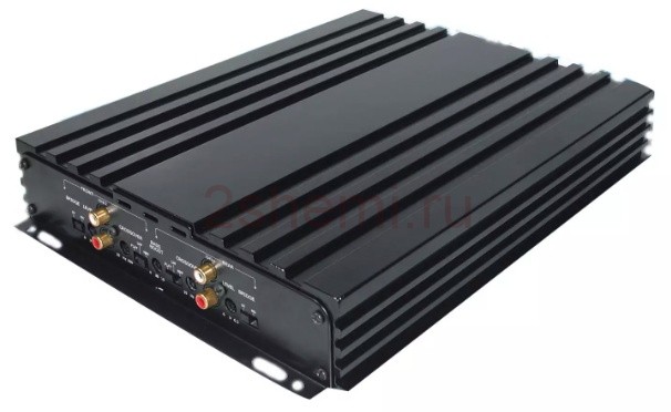
This, perhaps, was the most difficult moment in the manufacture, since there was no suitable finished case and I had to invent possible options :-)) In order not to sculpt a bunch of separate radiators, I decided to use a radiator case from a car 4-channel amplifier, rather large, something like this:
All the "insides" were, of course, extracted and the layout turned out to be something like this (unfortunately I did not take a photo):
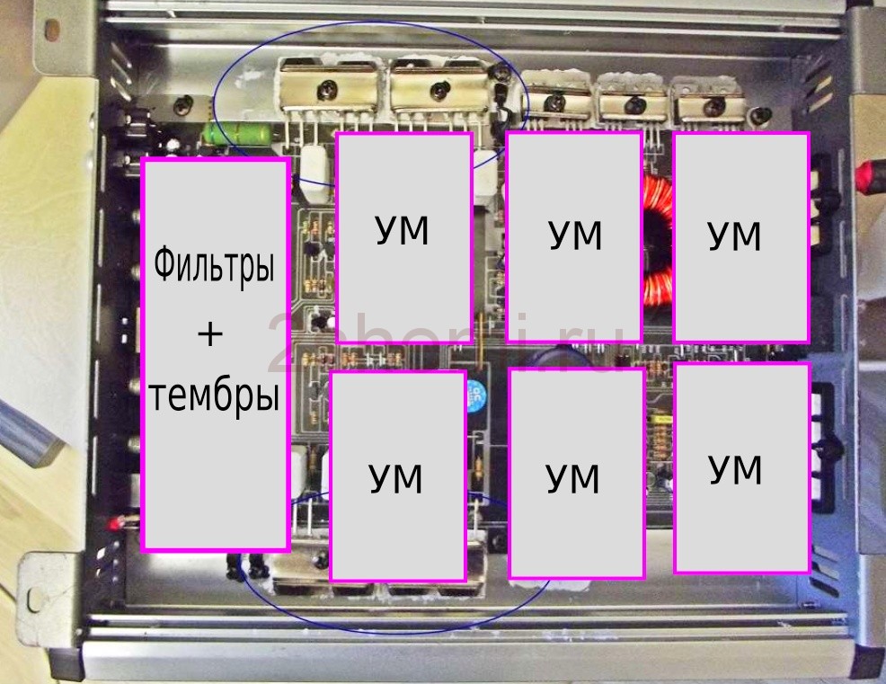
- as you can see, six terminal UMZCH boards and a preamplifier board were installed in this radiator cover. The filter block board did not fit anymore, so it was fixed on the then added construction from an aluminum corner (you can see it in the figures). Also, in this "frame" were installed transformers, rectifiers and power supply filters.
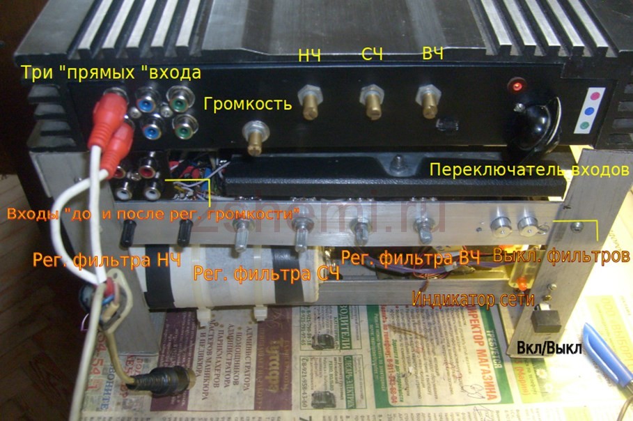
The front view with all the switches and controls looks like this:
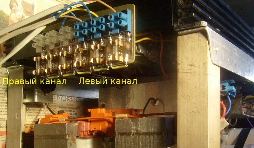
Rear view, with speaker output pads and a fuse box (since no electronic protection circuits were made due to lack of space in the design and in order not to complicate the circuit):
Subsequently, the frame from the corner is supposed, of course, to be closed with decorative panels to give the product a more "marketable" appearance, but this will be done by the "customer" himself, according to his personal taste. In general, in terms of sound quality and power, the design turned out to be quite decent. Author of the material: Andrey Baryshev (specially for the site site).


