Only one channel is described below. The second is completely identical. The amplifier is made on a modern integrated circuit TDA1514A manufactured by PHILIPS. Has the following characteristics:
- output power 50 W;
- load resistance RL 8 Ohm;
- nonlinear distortion 0.1%;
- supply voltage +/- 30 V;
- quiescent current 60 mA.
The TDA1514A microcircuit is manufactured in the SIL-9P package. In its structure, it has built-in cascades for overheating protection and short-circuit protection. It also has a loudspeaker turn-on delay stage, the time constant of which is determined by the values of the elements R2, C4. The gain of the circuit (10-200) depends on the ratio of R4 to R3.
Rice. 1. Electrical schematic diagram.
The amplifier, assembled from the elements of the kit, immediately works correctly and does not require adjustment. The IC should be screwed onto the aluminum heat sink. During operation, the microcircuit heats up quite a lot, and under continuous load at full power, the built-in overheating protection will turn off the amplifier.
|
4.7uF / 16V |
|
|
220 μF / 40 V |
|
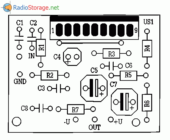
Rice. 2. Mounting plate.

Rice. 3. Printed circuit board.
During installation, you should pay attention to the fact that the "minus" of the power supply is connected to the radiator insert of the integrated microcircuit. Therefore, an insulating gasket can be used under the microcircuit, not forgetting to smear it with silicone grease or, by mounting the amplifier in a metal case, insulate the radiator.
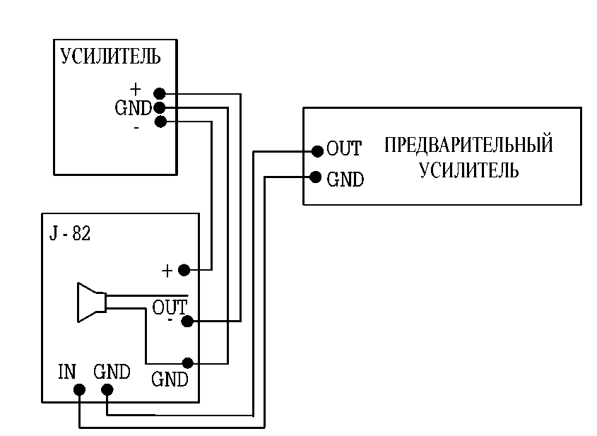
Rice. 4. Connecting the device.
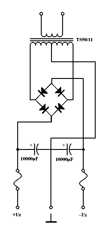
Rice. 5. Power supply circuit.
In order to fully utilize the capabilities of the described amplifier, it should be equipped with an appropriate power supply. It must provide a voltage not exceeding +/- 30 V (no load). The mains transformer must have a power of at least 120 W.
The capacitors used in each branch of the power supply must have a capacity of 10,000 mF. Correct connection of "masses" of the power supply, amplifier and preamplifier working with them is very important. This is shown in Fig. 4. Before turning on the amplifier, a resistor with a resistance of several tens of ohms and a power of several watts should be included in the positive branch.
This will protect the expensive microcircuit from damage in the event of a short circuit in the amplifier. After checking the quiescent current (> 60 mA with no signal per channel), the amplifier is ready for operation.
VRL - 100 best electronic circuits, 2004.


