This article will talk about such a demanded assistant to the radio amateur as a soldering station. At the time of this writing, I have found a very large number of different schemes of soldering stations - from the simplest to complex and sophisticated "monsters", which you will not find analogs in the store. I came up with the idea to assemble a soldering station a long time ago, but there was no desire to repeat someone's design, and there was no time to develop my own circuit. But a couple of months ago, a soldering station was urgently needed (I bought microcontrollers in TQFP cases, and an ordinary soldering iron not only had a thick tip, but it also mercilessly overheated and burned).
The device requirements were as follows:
- Possibility of memorizing temperature
- Optical mouse encoder control
- Using MK ATmega8 (they were in stock)
- Information display on LCD
Initially, it was not planned to reinvent the wheel, but simply to assemble one of the schemes presented on the Internet. But then, having estimated all the pros and cons, I decided to start drawing up my own scheme.
The result of the work is presented below:
** I was very surprised when I looked through the diagrams of soldering stations on the Internet. In almost all the variants I met, the op-amp was turned on simply according to the circuit of a non-inverting amplifier. In this design, a differential connection of an operational amplifier is used (the simplest option, but nevertheless, it works much better than a "simple" connection).
This circuit has one more feature - to power the LCD, I had to use a 3.3V stabilizer - LM1117-3.3. From it, the MK is powered along with the LCD. The operational amplifier is used for power supply 5V, which are removed from the linear stabilizer LM7805, located outside the printed circuit board, and therefore not shown in the diagram.
To control the load, a powerful field-effect transistor Q1 IRFZ24N was used, but since the potential of 3.3V is clearly not enough to open it, it was necessary to add a low-power bipolar transistor Q2 - KT315.
To display information, the device uses an LCD display from a Siemens A65 mobile phone (also found in A60, A62, etc.).
ATTENTION! A display with yellow textolite is required, bearing the inscription LPH8731-3C. Displays with a green background have other controllers that are not compatible with this one.
The display pinout is shown below:
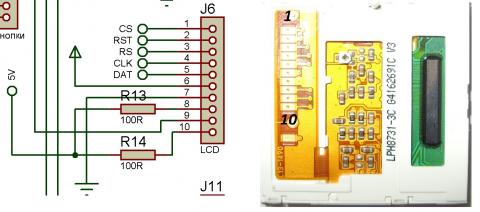
Output 6 is supplied with 3.3V from the LM1117-3.3 stabilizer, and the backlight is powered from 5V through 100 Ohm resistors.
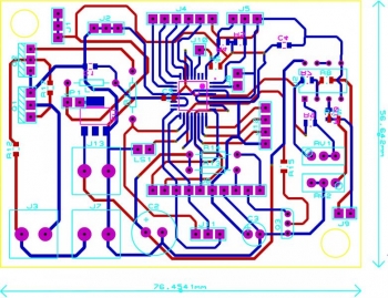
The printed circuit board is made on a double-sided foil material (textolite or getinax), and has dimensions 77x57 mm. It is designed for an ATmega8 microcontroller in a TQFP32 package, and therefore cannot boast of any particular simplicity. But it will allow you to cope with it without problems (I painted the tracks with varnish).
The topology of the PCB is shown below:
As a result, the device received the following features:
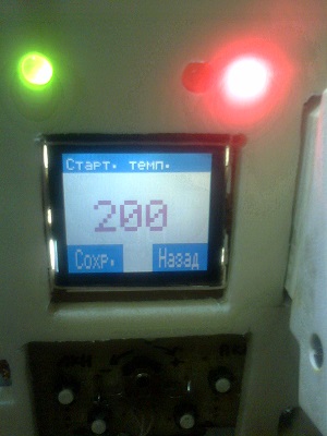
- Setting the initial (start) temperature
- Ability to set three profiles (temperatures), and quickly switch between them
- The values are adjusted using an encoder, which avoided additional buttons
- When the set temperature is reached, the sound signal is turned on (can be turned off in the menu)
- Pressing the buttons can also be accompanied by sound signals (can be disabled in the menu)
- The border of the sound signal can also be changed.
- PWM is used to maintain the set temperature
- It is possible to set the temperature limit, upon reaching which the PWM will turn on
- Backlight brightness adjustable
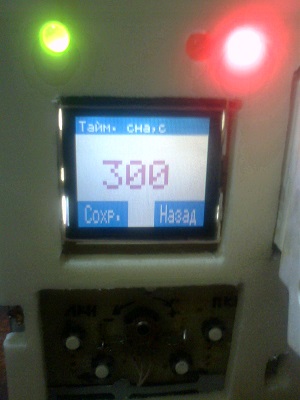
- There is a standby mode
- Standby temperature adjustable
- Time to standby is adjustable
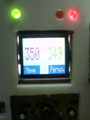
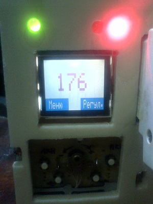
- Four temperature display options to choose from (only set, only real, set + real, set + real alternately)
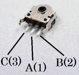
This circuit uses an encoder from an optical mouse, and it will not be difficult to get it.
Encoder pinout:
The microcontroller, alas, cannot be replaced even with a similar one without the "L" index, since the power supply of the circuit is 3.3V. The display has already been mentioned earlier. In the circuit, smd resistors of standard size 0805 are mainly used, but there are also 4 ordinary MLT-0.125. All capacitors, with the exception of electrolytic ones, are of the same standard size 0805. As a 3.3V stabilizer, you can use any one similar to LM1117-3.3, for example AMS1117-3.3. Instead of transistors BC547 and KT315, you can use any low-power silicon n-p-n structures, for example, KT312, KT315, KT3102, etc. Transistor IRFZ24N can be replaced with IRFZ44N, or similar. The program for the microcontroller is written in. I will not describe the code in the article, as this will entail a large amount of text.
If you have any questions, ask them in the comments, or in the forum thread.
All the necessary files for self-compilation of the project are in the archive attached to the article.
When programming the microcontroller, it is necessary to remove the JP1 jumper and connect it to the upper (according to the diagram) 5V contact from the programmer, bypassing the 3.3V stabilizer. Also, before programming, it is necessary to turn off the LCD display, since it is not intended for use with a 5V supply voltage (although it worked for me, but you should not risk it). I poured the firmware into the microcontroller using the program and the programmer.
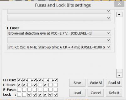
A screenshot of setting fuse bits is shown below:
To fine-tune the op-amp gain, it is necessary to set the knobs of the trimming resistors RV1 and RV2 so that the total resistance of RV1 + R7 and RV2 + R16 is exactly 100 times greater than the resistance of R8 and R10. Further, it is necessary to measure the real temperature of the soldering iron tip, for example, with a multimeter with a thermocouple, to check if the temperature value on the device screen and the multimeter data match. If the readings differ significantly, it is necessary to correct them with resistors RV1 and RV2.
A separate button (SB3) is provided for random activation / deactivation of the standby mode.
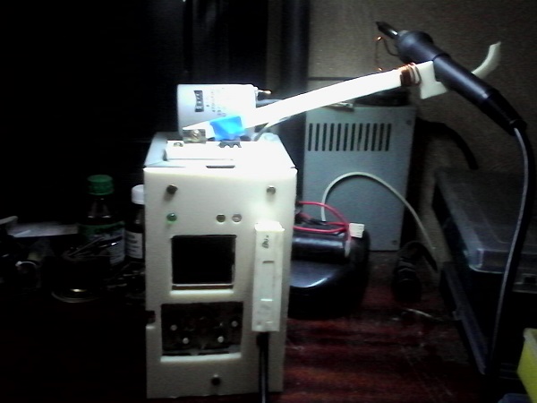
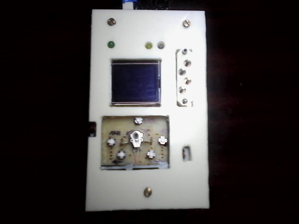
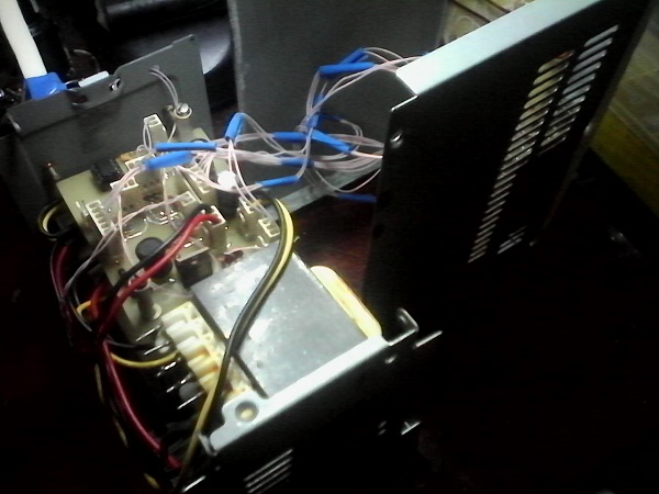
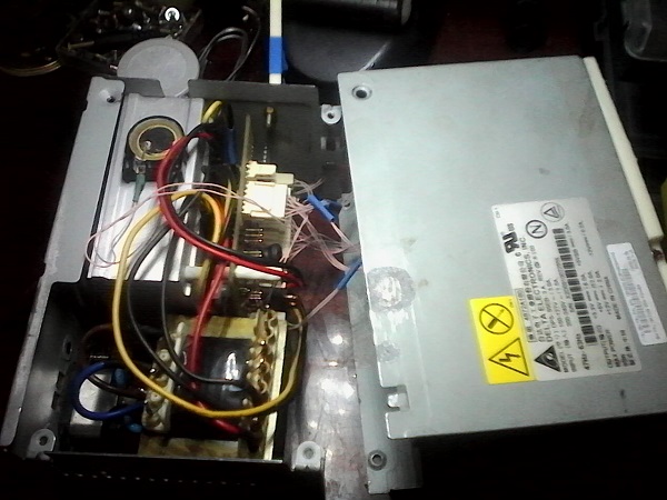
And finally, photos and videos of the device:
List of radioelements
| Designation | Type of | Denomination | Quantity | Note | Shop | My notebook | |
|---|---|---|---|---|---|---|---|
| U1 | MK AVR 8-bit | ATmega8-16PU | 1 | Index "L" | Into notepad | ||
| U2 | Operational amplifier | LM358N | 1 | Into notepad | |||
| U3 | Linear regulator | LM1117-3.3 | 1 | Into notepad | |||
| LCD1 | LCD display | LPH8731-3C | 1 | Yellow textolite | Into notepad | ||
| Q2, Q3 | Bipolar transistor | BC547 | 2 | Into notepad | |||
| Q1 | MOSFET transistor | IRFZ24N | 1 | Into notepad | |||
| R1 - R3, R13, R14, R17 | Resistor | 100 ohm | 6 | R1 - R3, R17 (0805), R13 - R14 (MLT-0.125) | Into notepad | ||
| R8, R10, R15 | Resistor | 1 kΩ | 3 | 0805 | Into notepad | ||
| R11 | Resistor | 4.7 k Ohm | 1 | MLT-0.125 | Into notepad | ||
| R6, R12 | Resistor | 10 kΩ | 2 | 0805 | Into notepad | ||
| R4, R5 | Resistor | 47 k Ohm | 2 | 0805 | Into notepad | ||
| R7, R16 | Resistor | 91 k Ohm | 2 | 0805 | Into notepad | ||
| RV1, RV2 | Trimmer resistor | 10 kΩ | 2 | Into notepad | |||
| C1, C4 - C5 | Capacitor | 100 nF | 3 | 0805 | Into notepad | ||
| C2, C3 | Electrolytic capacitor | 100 μF x 50 V | 2 | Into notepad | |||
| L1 | Inductor | 100 mH | 1 | Into notepad | |||
| D2 | Light-emitting diode | Red | 1 | 5mm | |||


