They often ask questions and complain about failures. To show that the alteration is really possible and it is not difficult at all, we have prepared another article, with illustrations and explanations.
Recall that you can remake any blocks, both AT and ATX. The first differ simply in the absence of a duty room. As a result, the TL494 in them is powered directly from the output of the power transformer, and, again, as a result, when adjusted at low loads, it simply will not have enough power, because. the duty cycle of the pulses on the primary transformer will be too small. The introduction of a separate power supply for the microcircuit solves the problem, but requires additional space in the case.
ATX power supplies here compare favorably in that nothing needs to be added, you just need to remove the excess and add, roughly speaking, two variable resistors.
On alteration - ATX MAV-300W-P4 computer power supply. The task is to convert it into a laboratory 0-24V, in terms of current - how it will turn out. They say that it is possible to receive 10A. Well, let's check.
Click on the diagram to enlarge
The power supply circuit is easy to google, but we can do without it, because we know that from the TL494 we need the inputs of both comparators, and these are pins 1, 2, 15, 16, and their common output 3, which is usually used for correction. We also release pin 4, since it is usually used for various protections. However, we leave the capacitor C22 and the resistor R46 hanging on it for a smooth start. We solder only the D17 diode, disconnecting the voltage monitor from the TL-ki.
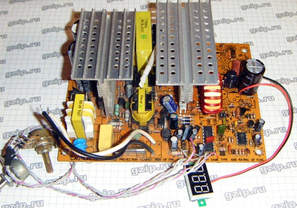
Add resistors, regulators, shunt. As the latter, two 0.025 ohm SMD resistors are used in parallel, which are included in the gap of the negative track from the transformer.
We connect the power supply to the network through a 200W incandescent lamp, which is designed to protect against breakdown of power transistors in case of an emergency. At idle, the voltage is perfectly regulated from almost 0 to 24 volts. What happens under load? We connect several powerful halogens and see that the voltage is already regulated up to 20 volts. This is to be expected since we are using 12V windings and a mid-point rectifier. On a powerful load, PWM is already at the limit and it is no longer possible to get more.
What to do? You can simply use the power supply to power not very powerful loads. But what to do if you really want to get the coveted 10 amps, especially since they are just declared on the power supply label for the 12 volt line? Everything is very simple: we change the rectifier to a classic bridge of four diodes, thereby increasing the voltage amplitude at its output. To do this, you need to install two more diodes. The diagram shows that such diodes were just installed, these are D24 and D25, along the -12 volt line. Unfortunately, their location on the board is unsuccessful for our case, so we will have to use diodes in "transistor" cases and either install separate heatsinks on them, or attach them to a common heatsink and solder them with wires. The requirements for diodes are the same: fast, powerful, for the required voltage.
With a converted rectifier, the voltage, even with a powerful load, is regulated from 0 to 24 volts, current regulation also works.
It remains to solve one more problem - the power supply of the fan. It is impossible to leave the power supply without active cooling, because the power transistors and rectifier diodes heat up according to the load. Normally, the fan was powered by a +12 volt line, which we turned into an adjustable one with a voltage range slightly wider than the fan needs. Therefore, the simplest solution is to feed it from the duty room. To do this, we replace the capacitor C13 with a more capacious one, increasing its capacity by 10 times. The voltage at the cathode D10 is 16 volts, and we take it for the fan, only through a resistor, the resistance of which must be selected so that the fan has 12 volts. As a bonus, you can bring a good five-volt + 5VSB power line from this PSU.
The requirements for the inductor are the same: with the DHS we wind all the windings and wind a new one: from 20 turns, 10 wires with a diameter of 0.5 mm in parallel. Of course, such a thick core may not fit into the ring, so the number of parallel wires can be reduced according to your load. For a maximum current of 10 amps, the inductance of the inductor should be in the region of 20uH.
A shunt built into an ammeter can be used as a shunt, and vice versa - a shunt can be used to connect an ammeter without a built-in shunt. The shunt resistance is around 0.01 ohm. By decreasing the resistance of the resistor R, you can increase the range of voltage adjustment upwards.


