Perhaps someone else remembers how the control panels of the first electronic computers (ECM) looked like. Today they can only be seen in archival photographs. Long rows of light bulbs, which flickered at first glance chaotically, fascinated electronics enthusiasts of those years.
The design of a binary clock presented in this article will help to recreate the atmosphere of previous years.
A schematic diagram of a simple binary clock is shown in Figure 1. The circuit is based on an ATmega48 microcontroller. There is no external real-time module (RTC) in the clock circuit, which in turn somewhat reduces the cost of the device.
In case of a possible power failure from an external source, the timing is maintained by the built-in CR2032 battery, while the LEDs are turned off. To detect the supply voltage from an external power supply, a circuit with a VT1 transistor (BC847) is used.
If there is voltage at the terminals of the power connector, then it passes through the diode D1, as a result of which the transistor enters the saturation state, and a logic zero is applied to the PC0 input of the microcontroller, which triggers the operation of the LEDs.
The indication of the current time (hours, minutes and seconds) is realized using three lines of LEDs. The LEDs are controlled by multiplexing, which reduces power consumption and reduces the number of microcontroller pins used.
Viewing is carried out only in a 24 hour format. To display the number of minutes and seconds, 6 LEDs are needed, and for hours, 5 LEDs.
The ATmega48V-10AU microcontroller is capable of operating at reduced power supply down to 1.8V, which is a great advantage. In addition, the ATmega48V-10AU draws less current. The clock signal frequency is stabilized by a 4 MHz quartz resonator, which is also a reference for timing.
Setting the current time (hours and minutes) is carried out using the SW2 and SW1 buttons, respectively. The seconds counter is reset to zero when you press any of the buttons.
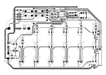
It is worth noting that these buttons are inactive when running on battery backup to prevent the possibility of inadvertently changing the time. The watch is assembled on a single-sided printed circuit board measuring 103mm × 67mm.
When programming the microcontroller, it is necessary to set the microcontroller to work from an external crystal 4 MHz crystal and turn off the division of the clock frequency by 8 (this bit is called CKDIV8).
After correct assembly, the clock starts working immediately and should show 00:00:00.
The circuit is powered from a power supply with a voltage of +5 V. Backup power - a CR2032 battery is optional, it only maintains a countdown after a power failure.
The current consumption from the battery is about 1.5 mA. With a battery capacity of about 200 mAh, it should be enough for 5 or more days of operation of the microcontroller, which is sufficient in typical situations.
As already mentioned, the display of time is carried out in a binary system. The most significant bits are on the left and the least significant bits are on the right. The hours, minutes and seconds are intentionally not signed on the watch, so that it would be difficult for uninitiated people to guess how the clock works.


