Large LED clock
Introduction.
It all started like that. At the dacha, I had an old mechanical alarm clock (made in USSR), which had problems with the mechanics. I decided to collect an electronic clock. The first problem is which indicator to choose. VLI and GRI are not suitable due to large temperature differences in the country. The LCD is omitted for the same reason. The LED indicator remains. I'm tired of looking at small numbers on indicators, and large seven-segment ones are rare and expensive. It was decided to make an indicator with a digit height of 50mm from separate green LEDs.
We figured out the indicator, but it needs to be controlled somehow. In this case, the clock should run even with a prolonged lack of power. We will do it on the ATTiny2313 MK and the RTC DS1307 microcircuit, which also has a built-in power controller and allows you to connect a battery.
1. Indicator.
We will do, as I said, from individual green LEDs with a diameter of 5 mm. Here is the diagram of the indicator:
There is nothing special to explain here. Current-limiting resistors, diodes are needed for beautiful drawing of numbers. Each rectangle on the diagram must have one digit (the diagram is the same for all), in the middle - a separating colon.
2. The main part.
The circuit, as I said, is based on ATTiny2313 and DS1307. There she is:
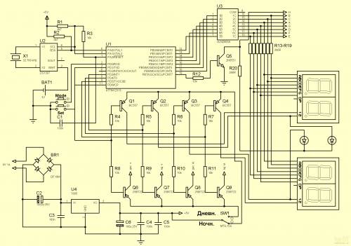
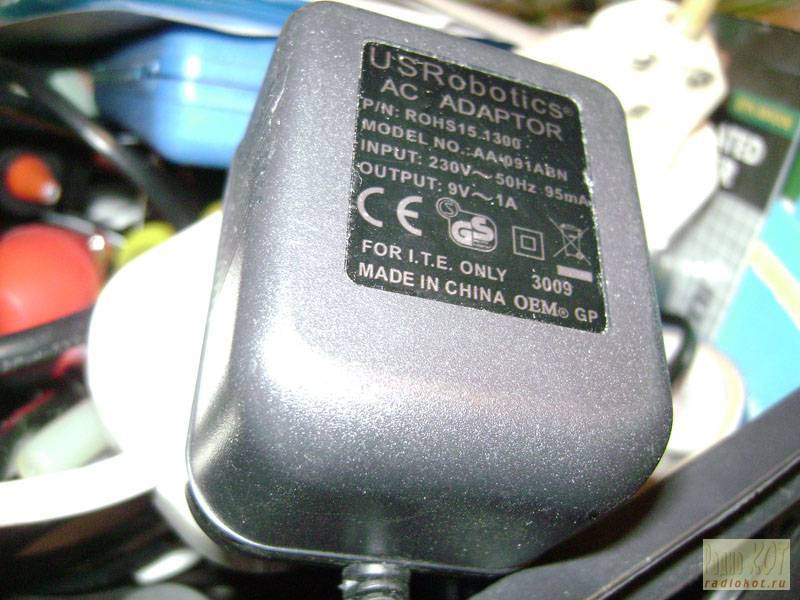
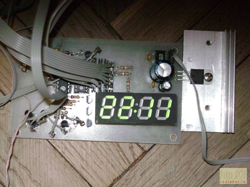
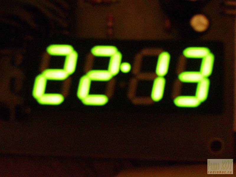
Explanations are required here. On the right, there are two double seven-segment devices and two LEDs - the internal circuit of a small indicator with OA. Why two indicators? At night, the large indicator with a bright glow can interfere with sleep (the clock will be near the bed), so the indication can be switched to the small indicator with the SW1 switch. In the "Night" position a small indicator works, in the "Day" position. - big. I took this little indicator out of the washing machine, there is a pinout on the cookie. 3V battery, CR2032. Transistors Q1-Q4 can be replaced with any other low-power PNP transistors, for example, KT315. Q6-Q9 - for PNP with a CE current of at least 1A, Q5 - for NPN with a collector current of at least 0.4A. The power supply can be any with a voltage of 9-20V, polarity is not important, you can even start up a change. Current not less than 1A. The U4 stabilizer must be installed on the radiator. By the way, the lower the input voltage, the easier life is for the stabilizer. I have a power supply unit like this:
Now let's move on to the assembly.
3. Build.
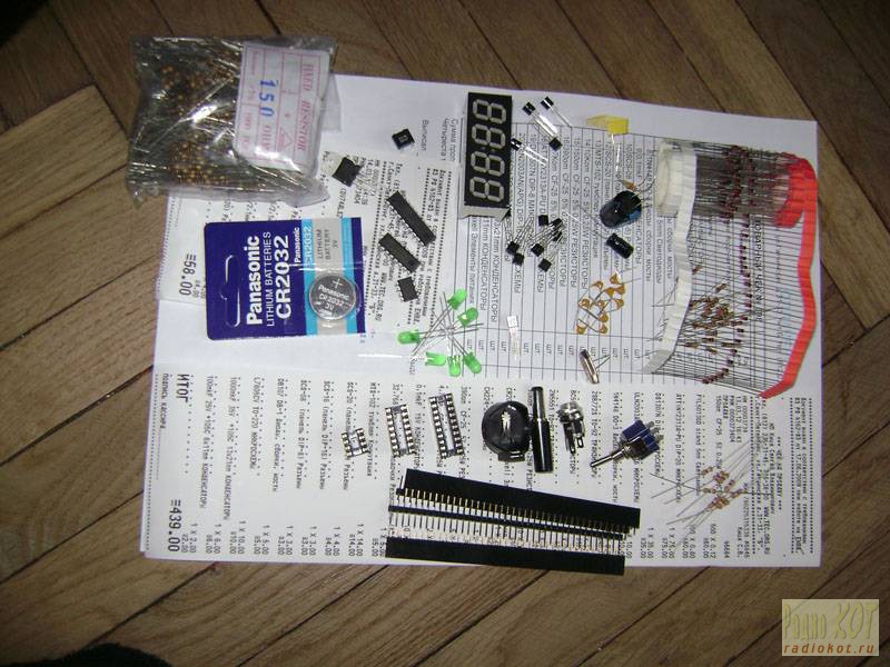
We go to the store and buy parts.
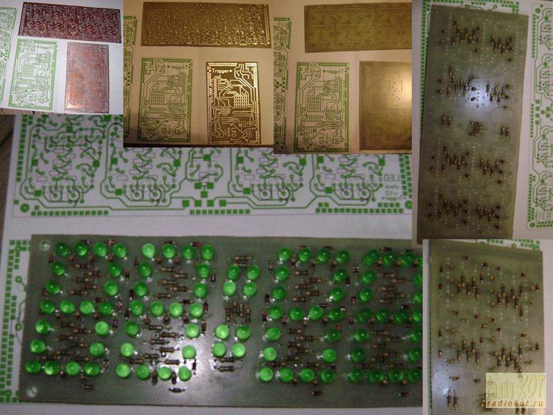
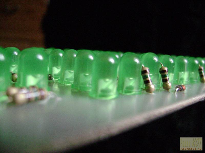
We make the boards and start soldering. Soldering 88 LEDs, the same number of resistors and 44 diodes is not easy, but worth it.
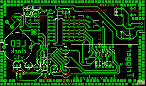
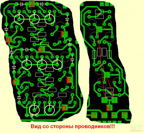
Now we connect everything with wires. I use PLS / PBS loops and connectors. These pictures will help you:
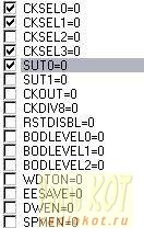
Now we are flashing the MK. Here are the fuses:
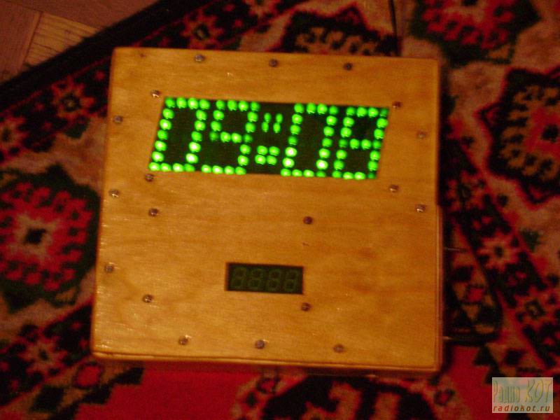
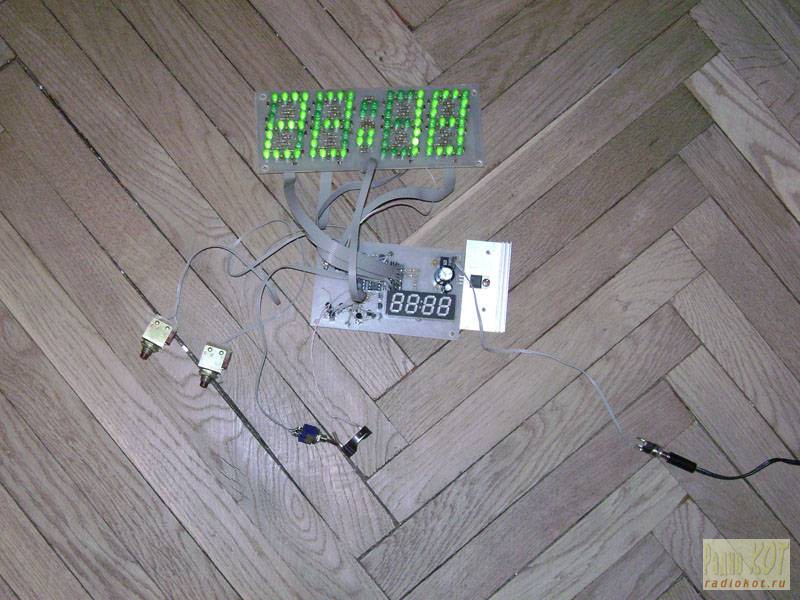
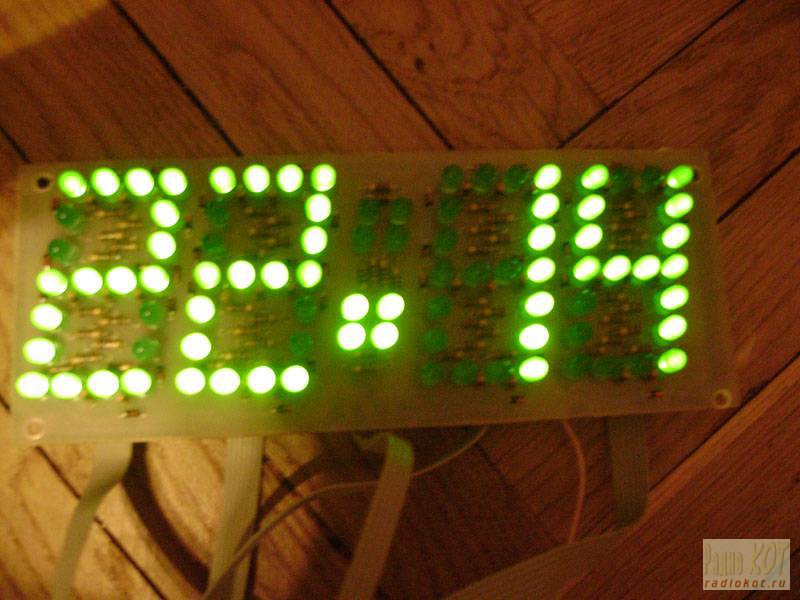
And turn on:
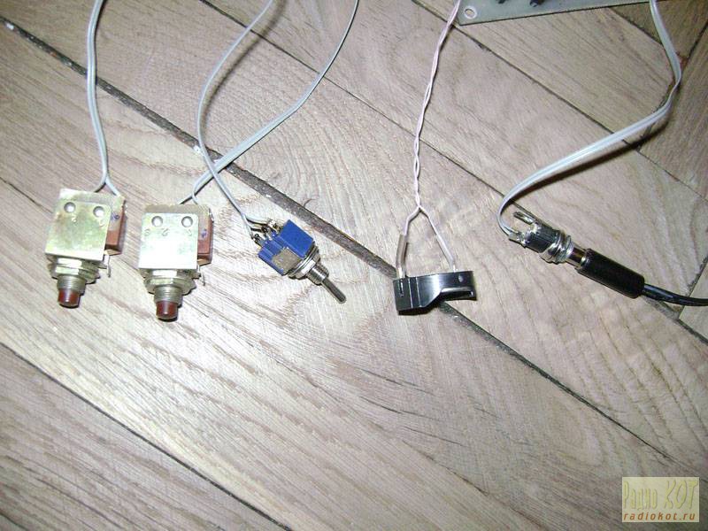
I used the buttons and connectors:
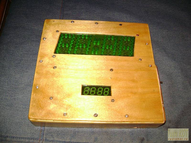
4. Housing.
I made the body of plywood and a 20 * 40 bar, sanded and varnished. At the back I put two fasteners for mounting on the wall.
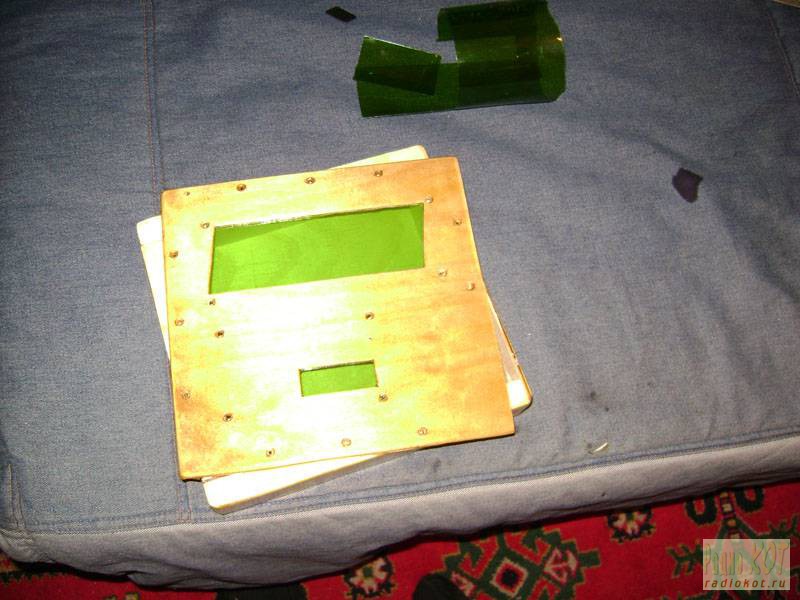
By the way, to seal the windows for the indicators, I used a film from green bottles, it looks beautiful and protects from sunlight exposure.
Now a few photos: