After I was finally exhausted by my 40 W soldering station of unknown origin, I decided to create a professional-level soldering station with my own hands at ATMega8.
There are inexpensive products from different manufacturers on the market (for example, AIOU / YOUYUE, etc.). But they, as a rule, have some significant defect or controversial design.
I warn you: this digital soldering station is needed to solder the only one, without unnecessary decorations such as AMOLED displays, touch panels, 50 operating modes and Internet control.
But still, it will have several features that will be useful to you:
- inactive mode (maintains a temperature of 100-150 ° C when the soldering iron is on the stand.
- automatic shutdown timer so that forgetfulness does not cause a fire.
- UART for debugging (for this assembly only).
- additional connectors on the board for connecting a second soldering iron or hair dryer.
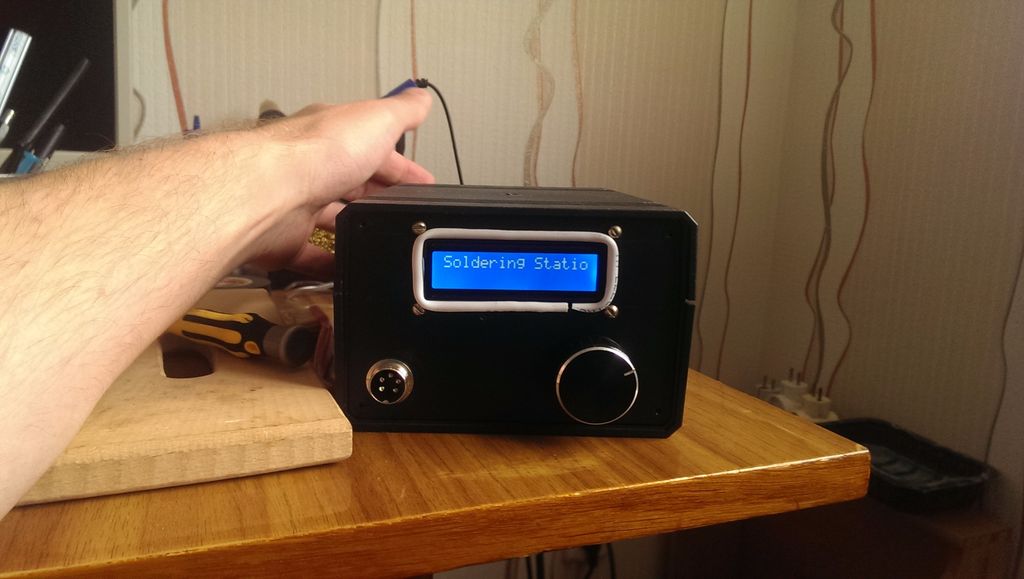
The interface is simple enough: I made two buttons, a rotary encoder and a 16x2 LCD (HD44780).
Why do the station yourself
A couple of years ago I bought a soldering station over the Internet, and although it still works well, I got tired of working with it because of its stupid design (short power cord, no compressor blown and short non-detachable tip cord). Due to design flaws, it is inconvenient to rearrange this station even on a table, the body turns after the sting. The insides were filled with hot melt glue, a week was spent only on cleaning the components and eliminating minor and major deficiencies.
The fastening of the cord of the soldering iron stand was kept on parole, the insulation was constantly getting lost, and this is a wire break, and a possible fire.
Step 1: Materials Required
List of materials and components:
- Converter 24 V 50-60W. My transformer has a 9V secondary line that will go to logic gates while the primary line will go to a soldering iron. You can also use a 5V buck converter for the cells, and separately the inner contents of the 24V power supply for the soldering iron.
- Microcontroller ATMega8.
- Frame. Any box made of solid material will do, preferably metal, you can take the case from the power supply. You can order such a case.
- Double-sided copper plate 100x150 mm.
- Rotary encoder from an old cassette recorder. Works great, just replace the regulator cap.
- LCD HD44780 16x2.
- Radio components (resistors, capacitors, etc.).
- Voltage stabilizer LM7805 or similar.
- The heatsink is no larger than the TO-220 package.
- Replacement tip HAKKO 907.
- MOSFET IRF540N.
- Operational amplifier LM358N.
- Bridge rectifier, two pieces.
- 5-pin socket and plug to it.
- Switch.
- Plug of your choice, I used a connector from an old computer.
- 5A fuse and fuse holder.
Assembly time is approximately 4-5 days.
As far as the power supply is concerned, you can make quite viable versions / additions. For example, you can get a 24V 3A power supply using the LM317 and LM7805 to drop the voltage to.
All parts from this list can be ordered from Chinese Internet sites.
Step 2: Day one - think over the electrical circuit
The HAKKO 907 soldering iron has many clones, there are still two varieties of original soldering tips (with ceramic heating elements A1321 and A1322).
Cheap clones are examples of early replicas, using a XA thermocouple and a lousy quality ceramic heater, or even a nichrome coil.
The clones are slightly more expensive, almost identical to the original HAKKO 907. You can determine the originality by the presence or absence of markings on the braid of the HAKKO brand wire and the model number on the heating element.
You can also determine the authenticity of the product by measuring the resistance between the electrodes or wires of the heating element of the soldering iron.
Original or quality clone:
- Heating element resistance - 3-4 Ohm
- Thermistor - 50-55 ohms at room temperature
- between tip and ESD ground - less than 2 ohms
Bad clones:
- On the heating element - 0-2 ohms for a nichrome coil, more than 10 ohms for cheap ceramics
- on thermocouple - 0-10 Ohm
- between tip and ESD ground - less than 2 ohms
If the resistance of the heating element is too high, it is most likely damaged. It is better to exchange it for another one (if possible) or buy a new ceramic element A1321.
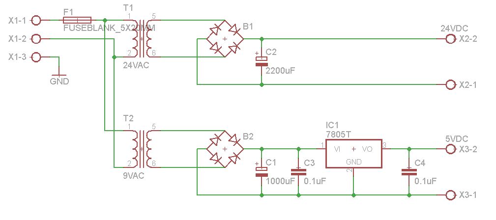
Nutrition
So that you do not get confused in the circuit, the converter is depicted on it as two converters. The rest of the diagram is pretty simple and you shouldn't have any difficulty reading it.
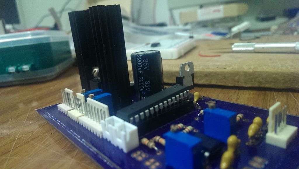
- We install a bridge rectifier at the output of each secondary voltage line. I bought some good quality 1000V 2A rectifiers. The converter on the 24V line gives out a maximum of 2A, and the soldering iron needs a power of 50W, the total calculated power will be approximately 48W.
- A smoothing capacitor 2200 microfarads 35 V is connected to the 24V output line. It seems that it was possible to take a smaller capacitor, but I have plans to connect additional devices to a self-made station.
- To reduce the supply voltage of the control panel from 9V to 5V, I used an LM7805T voltage regulator with several capacitors.
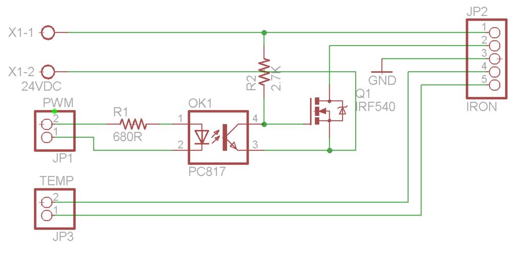
PWM control
- The second diagram shows the control of a ceramic heating element: the signal from the ATMega microcontroller goes to the IRF540N MOSFET through the PC817 optocoupler.
- The values of the resistors in the diagram are conditional and can be changed in the final assembly.
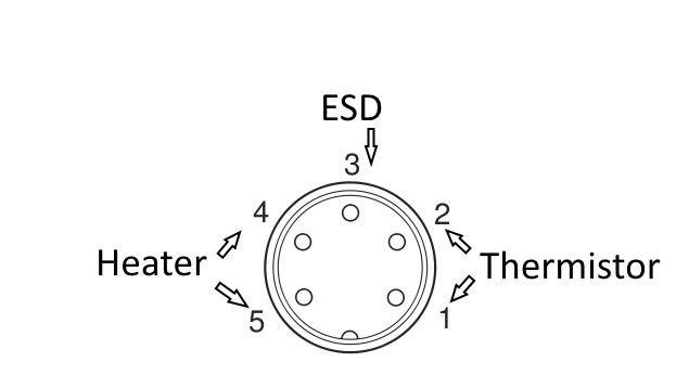
- Pins 1 and 2 correspond to the heating element wires.
- Pins 4 and 5 (thermistor) are connected to the connector to which we connect the LM358 operational amplifier.
- The ESD ground of the soldering iron is connected to pin 3.
Connections to the controller board
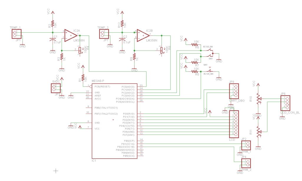
The soldering station is based on the ATMega8 microcontroller. There are enough connectors on this microcontroller not to use shift registers for I / O and greatly simplifies the design of the device.
The three OS pins for PWM provide enough channels for future additions (for example, a second soldering iron), and the number of ADC channels makes it possible to control the heating temperature. The diagram shows that I added an additional channel for PWM and connectors for a temperature sensor for the future.
In the upper right corner there are connectors for the rotary encoder (A and B for directions, plus a switch button).
The connector for the LCD is divided into two parts: 8 pins for power and data (pin 8), 4 pins for contrast / backlight settings (pin 4).
The ISP connector is not included in the circuit. To connect the microcontroller and reprogram it at any time, I installed a DIP-28 connector.
R4 and R8 control the gain of the respective circuits (up to a maximum of one hundred times).
Some details will be changed during assembly, but in general, the scheme will remain so.
Step 3: Day 2 - preparatory work
The enclosure I ordered was too small for my project, or the components were too large, so I replaced it with a larger one. The downside was that the size of the soldering station increased accordingly. But it became possible to add additional devices - a diode lamp for comfortable work, a second soldering iron, a connector for a soldering tip or a smoke remover, etc.
Both boards were assembled into one unit.
Preparation
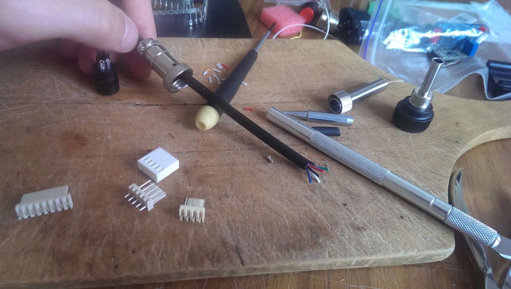
If you are lucky enough to find a suitable socket for your HAKKO soldering iron, skip two paragraphs.
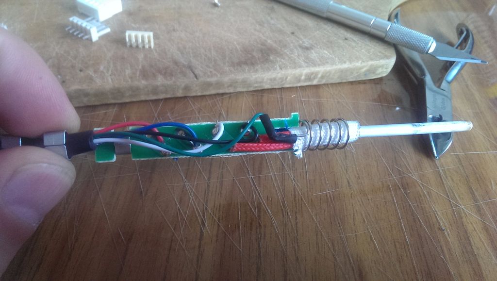
First, I replaced the original plug on the soldering iron with a new one. It is all-metal and with a locking nut, which means that it will always be in its place and practically forever. I just cut off the old 5-pin plug and soldered a new one in place.
For the connector, we drill a hole in the wall of the case. Check if the connector fits into the hole and leave it there. We'll install the rest of the front panel components later.
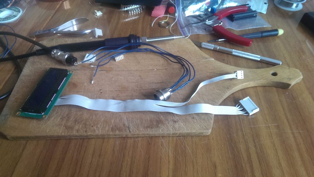
Solder 5 wires to the connector and fit the 5-pin connector that will go to the board. Then cut out the holes for the LCD, rotary encoder and 2 buttons. If you want to bring the power button to the front panel, you also need to cut a hole for it.
The last photo shows that I used a ribbon cable from an old floppy drive to connect the display. This is a great option, you can also use an IDE ribbon cable (from the hard drive).
Then connect the 4-pin connector to the rotary encoder and if you have installed buttons, connect them as well.
It would be nice to drill 4 holes for mounting small screws in the corners of the cutout for the display, otherwise the display will not stay in place. On the back panel, I brought a connector for the power cord and a switch.
Step 4: Day 2 - Making the PCB
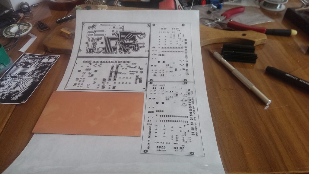
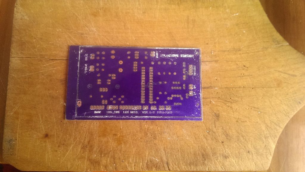
You can use my drawing for the PCB, or make your own one that meets your requirements and specifications.
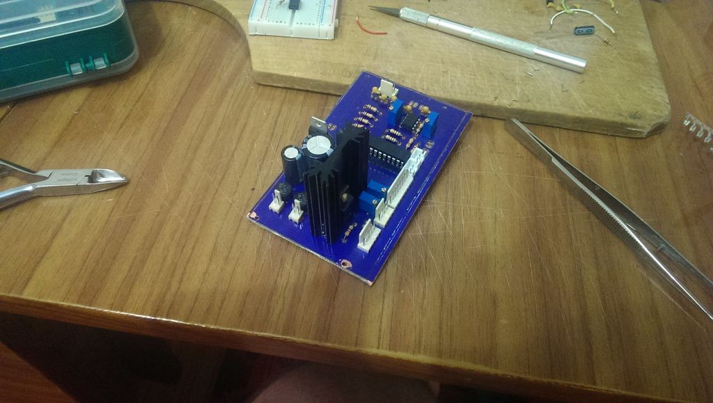
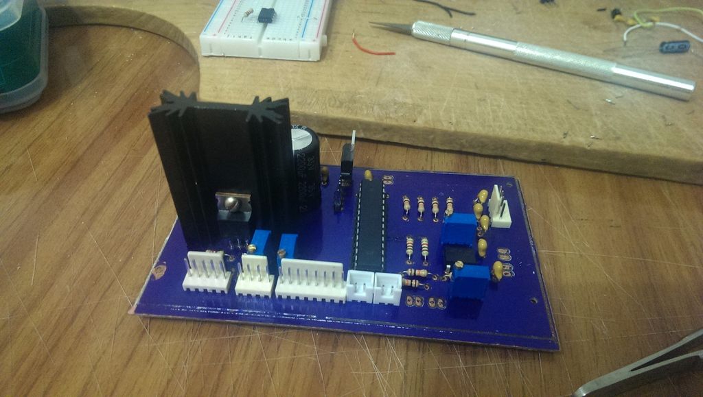
Step 5: Day 3 - Completing the Build and Encoding
At this stage, be sure to check the voltage at key points of your unit (5VDC, 24VDC outputs, etc.). The LM7805 regulator, IRF540 MOSFET and all active and passive components should not heat up at this stage.
If nothing has heated up or caught fire, you can collect all the components in place. If your front panel is already assembled, all you have to do is solder the converter wires, fuse, power connector, and switch.
Step 6: Days 4-13 - Firmware
I am using raw and untested firmware for now, so I decided to postpone posting it until I write a self-diagnostic debug routine. I would not want your home or workshop to be damaged by fire, so please wait for the final publication.


