One fine moment I needed a power amplifier for the house, which would be part of the complex: Priboy E104S -> Radiotehnika UP-001 -> Power amplifier -> VEGA 50AS-106. The requirements were as follows: decent sound quality, use of the existing construct. At the same time, I did not limit myself to ready-made circuitry studies on the network or in radio amateur literature, but tried to create my own amplifier, based on the experience and material available. This article is devoted to this amplifier.
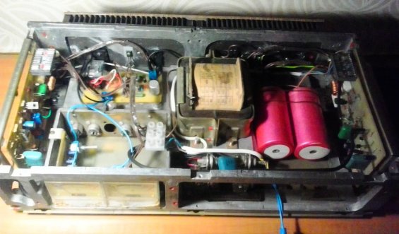
Since the electrical filling is still not so bad, and for a radio amateur, finding a hull is a headache that undermines the national health of our country, the problem of the hull should be touched upon first. There are many options for solving the problem, I decided to take as a basis the case of the Soviet amplifier "Electron 104-stereo" produced in 1977, and I strongly recommend everyone to look for this faulty amplifier for the future case and for profitable borrowing of a step-down transformer (which will also be the main power element of the amplifier ). These amplifiers were almost universally used in theater circles, schools, kindergartens in assembly halls. I am talking about the time to start making "friends" in schools. The cabinet of this amplifier is a prime example of the wasteful use of aluminum, which makes it possible to use the possibilities of the cabinet design for powerful amplifiers. At the same time, the disadvantage of this case is the proximity of one of the channels to the power transformer (blue arrow), which can give rise to such a phenomenon as the presence of a background amplifier in one of the channels, with a frequency that is a multiple of the mains frequency. Therefore, it was decided to move the location of the diode bridge (green arrow).
The power supply circuit has no special features and is actually the power supply circuit of the original amplifier, but with a modified design. The final stage for placing all electrical components is illustrated below.
Now you can go to the electrical part. The amplifier is a classic Lin topology, with changes and additions. Amplifier parameters:
Characteristic - The magnitude:
- Supply voltage range: ± 24 ... 35V
- Frequency response band, not already: 20-20000Hz
- Effective Power Output, @ 4 ohm load and ± 35V supply: 80W
- Harmonic distortion at maximum output power and input signal - 1kHz sine wave: 0.004%
- Harmonic distortion at maximum output power and input signal - 20kHz sine: 0.02%
- Signal-to-noise ratio, at a frequency of 1 kHz, not less - 95 dB
Sound amplifier circuit
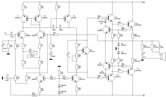
The input stage of the power amplifier is assembled according to a differential circuit on transistors T3 and T4, loaded on a stable current generator, made according to the traditional classical circuit on a transistor T5. Resistors R3, R4, R6, R7 are included in the emitters of the transistors of the differential stage, which play the role of local feedback, thus reducing the nonlinearity of the internal resistance of the emitter junction. In the collector area of the input stage, a current mirror is included on the elements T1 and T2, with additional resistors in the emitters to reduce the influence of the Earley effect, to achieve a more accurate balancing of the input stage.
Further, the second stage of the amplifier is made on the transistor T6 according to the voltage amplifier circuit and includes a two-pole correction. The bias circuit is made according to the "transistor zener diode" circuit using the T8 element. Installed on the radiator together with the output stage, it also performs the function of a thermal stabilizer. The inclusion of the quiescent current adjustment resistor R22 is made in such a way as to ensure the safety of the circuit against accidental breakage of the motor of the removable contact, and in this regard, to prevent a sharp increase in the quiescent current of the output stage. The bias current is also fed from a stable current generator on the T7 transistor, which has a common reference voltage source with the generator for the differential stage (diodes D1, D2). The output stage is made according to the symmetrical scheme of switching on the emitter followers. The output signal passes through the R37L2 output filter and the Sobel circuit (R36C8), which prevents the amplifier from self-oscillating at high frequencies.
Few oscillograms
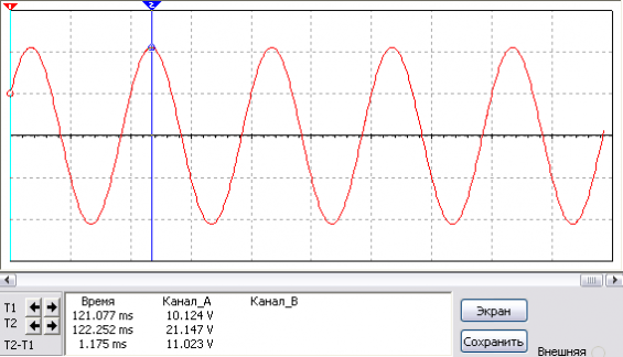
1) Sine 1kHz, 80W
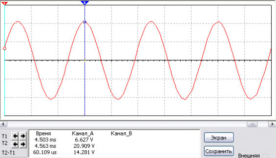
2) Sine 20kHz, 80W
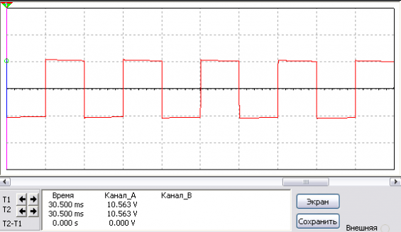
3) Square wave 1kHz
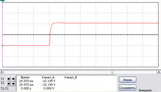
4) Square wave 1kHz
Construction and details of home audio amplifier
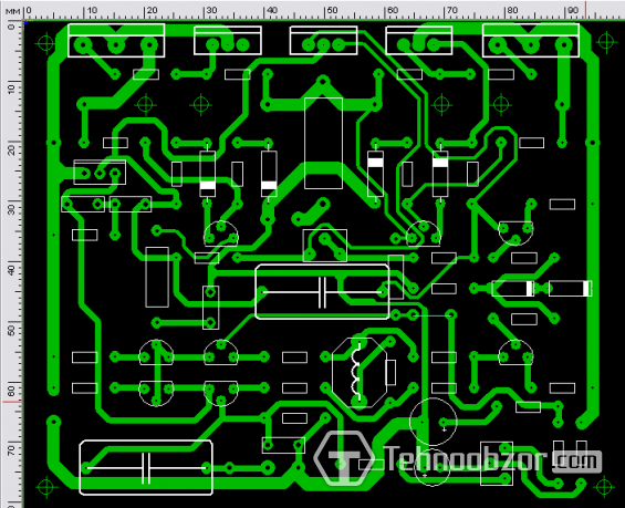
The L2 coil is wound on any pencil (pull the pencil out of the coil) with a 1 mm wire and contains 10-12 turns. The T8 transistor is installed on the heat sink, along with the output transistors. All transistors must be isolated from each other through mica spacers. To reduce the effect of temperature changes on the value of the constant voltage at the output of the amplifier, it is recommended to press the transistors T1, T2 and T3, T4 in pairs with each other with PVC ties or heat shrinkage. T9-T10 elements are located on separate aluminum plates (radiators) with a dispersion area of 30-40 cm2. The drawing of the printed circuit board is made for the existing construct, in my case the drawing was drawn on paper with a pencil. A top view of the general-purpose PCB looks like this (not tested or validated, errors are possible). its file can be found here.
ULF setting
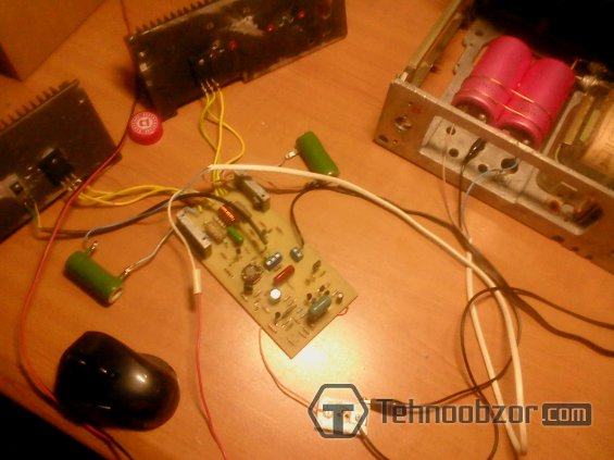
The first connection must be made through current-limiting resistors in the power supply, as well as with an equivalent load, after warming up and making sure that all the nodes of the circuit are working normally, i.e. do not cause stressful situations for you and those around you. After that, a full power supply is supplied to the amplifier, without removing the equivalent resistance. The trimmer R15 achieves zero at the amplifier output, and the trimmer R22 sets the quiescent current, in the range of 40-50 milliamperes. Result: really lively and good sounding, excellent lows (and this is on the 50AC-106!), 4 copies were collected, all started the first time.


