Guitar amplifiers, along with the electric guitars themselves, have always interested many beginners and not only musicians. Timbre, gain, and drive characteristics are very individual, and the ideal combination will vary from one guitar to the next. There is no amplifier that fully meets all the requirements, and this circuit proposal will be no exception. But it is versatile, powerful (about 100 watts) and has all the necessary adjustments. Unlike a commercially available amp, if you build the ULF yourself, you can change many things to suit your own needs. The opportunity to experiment is presented in full. And it is much more honorable to play on our own equipment, because our individuality is manifested primarily in creativity. This guitar amp is rated at 100 watts into a 4 ohm load. This is the usual power for guitarists, which is enough for both home and concerts.
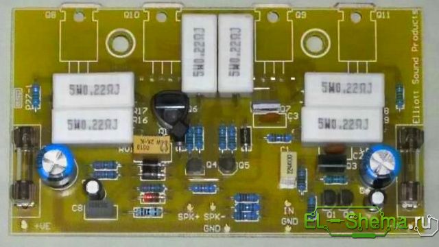
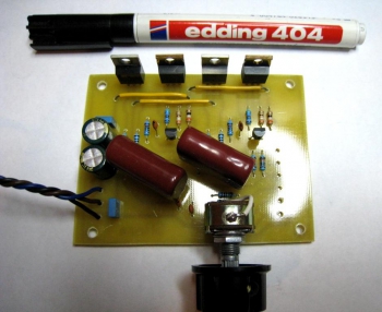
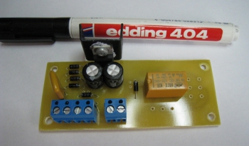
We solder the preliminary guitar amplifier on a separate board, which is later placed in the noise shield. A photo of the preamplifier board is shown below. Its basis is two operational amplifiers with a tone and gain control unit.
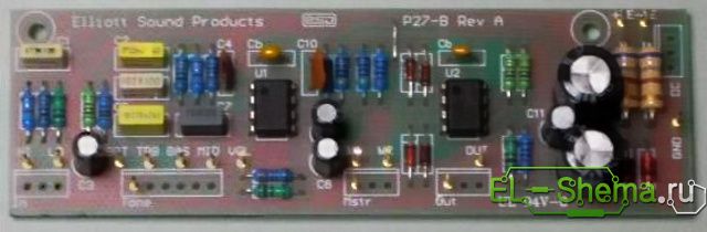
This is a simple but proven circuit design that provides excellent tonality across the entire range. The design is ideal for guitarists looking for great sound. The tone controls have enough range to cover just about anything from violin to bass.
The preamplifier uses a dual operational amplifier for amplification. The transistor is connected according to the emitter-follower scheme and has a low output impedance, after the master volume control. As shown in the diagram, there is a typical guitar input from which you can get very fat overdrive and then adjust to an appropriate level. Please note that when using the TL072 operational amplifier, noise may occur with big amount high frequencies. It is highly recommended to use the OPA2134, an operational amplifier from Texas Instruments, then you will have the truly quietest guitar amplifier you have ever heard!
The module power supply is connected directly to the main +/- 35 V bus of the power amplifier. You need to use zener diodes (D5 and D6) 1 W, and resistors R18 and R19, 680 Ohm, should also be 1 W.
For more gain, we advise you to reduce R11 - to at least 2.2 kOhm. If the bright switch makes the sound too bright (too much high frequencies), you need to increase the resistor R5. The diodes on the output are designed to cause the preamplifier to create "soft" clipping as the volume rises.
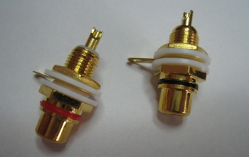
Make sure the input connectors are insulated from the chassis. This helps prevent noise, especially when the guitar amp is connected to a different mains supply.
Amplifier
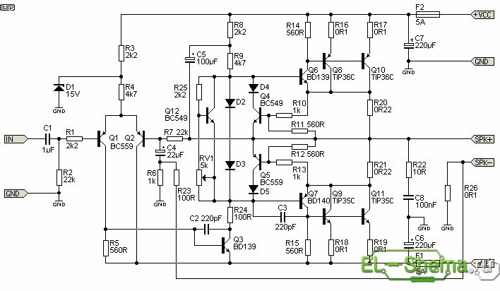
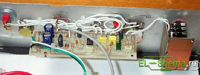
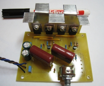
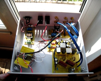
The photo below shows a fully assembled UMZCH printed circuit board. With TIP35 and TIP36 output stage transistors, reliability is ensured in the harshest stage environments. Other features of the circuit include protection against short circuit- bias components of diodes D2 and D3.
Short circuit protection limits the output current to a relatively safe level. The protection will limit the peak output current to approximately 8 amps. The bias current is adjustable and should be set at about 25 mA at rest. Transistors TIP3055 / 2966 or MJE3055 / 2955 can also be used for UMZCH. The circuit allows you to connect up to two 8-ohm speakers (4 ohms each). Do not use speakers less than 4 ohms with this amplifier - it is not designed for such low impedance!
ULF power supply
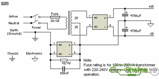
The power transformer must be toroidal for best performance and minimum interference. The amplifier is designed for a maximum supply of +/- 35V and this value must not be exceeded. The transformer should be rated for 25-0-25 volts, and no more. Less is fine if you don't need the full 100 watts. The transformer power must be 150VA (3 A secondary current). Over 250VA is overkill. Use good quality PS filter electrolytes, as they will be subjected to current and temperature loads. The current of the diode bridge rectifier must be 35 A. The type of mounting is on the chassis with thermal grease.
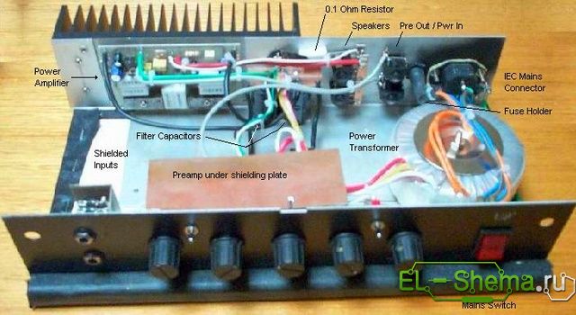
All fuses should be as shown in the diagram - resist the temptation to use more powerful ones. The input and output connections are shown in the figure.
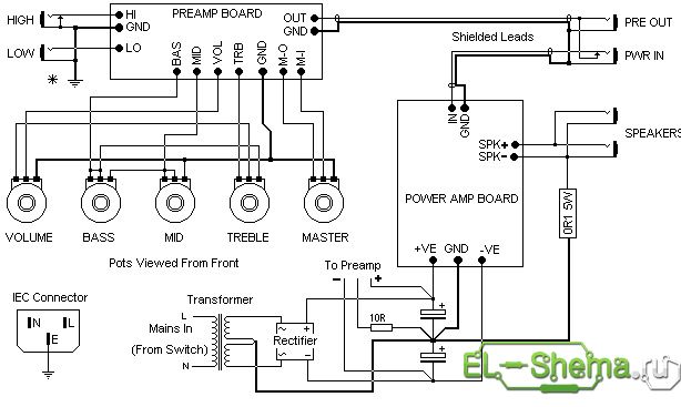
Nests Preamp out and power amp in allow you to insert effects into the sound path, such as compression, reverb, digital effects and others. The preamplifier output is connected so that the preamplifier signal can be extracted without disconnecting the power amplifier, so it can be used for direct sound delivery. This is especially useful for bass. The preamplifier output can also be used for.
Guitar Amp Tuning
- Before powering on for the first time, temporarily install 22 ohm 5W resistors in place of the fuses. Do not immediately connect the load (AC)! When applying power, check that the DC output voltage is less than 1 V. Check all transistors for heat - if any element is hot, immediately turn off the power, then look for an error.
- If all is well, connect the speaker system and signal source and make sure that the sound is not distorted (for example, connect music from the player).
- If the ULF passes all of these tests, remove the 22 ohm resistors and reinstall the fuses. Disconnect the speaker load cable and turn on the instrument again. Make sure the DC voltage across the AC terminals does not exceed 100 mV, and again check the heating on all transistors and resistors.
- When you are satisfied that everything is good, set the bias current. Connect a multimeter between Q10 and Q11 collectors - you are measuring the voltage drop across two 0.22 ohm resistors R20 and R21. The quiescent current required is 25 mA, so the voltage across the resistors must be set to 11 mV. Setting the value is not too critical, but at lower currents there will be less dissipation on the output transistors.
- After that, it remains to correct the offset, when the temperature of the body and all parts of the guitar amplifier stabilizes. Temperature and current are often slightly interdependent. That's all - the design is ready!
I didn't want a circuit on an operational amplifier, because I had already assembled it, I wanted something more interesting. And in my search on the Internet, I came across a circuit that used field-effect transistors of the same conductivity. Unfortunately, on the diagram that I found there were not all the denominations of the parts, and there were no markings of the transistors. And the circuit itself was more like scanned sheet, magazine. But something told me that the scheme was not bad, especially since there were not many details there. Why not build on a breadboard and experiment?
After a certain time, the scheme that I came across began to look like this:
Transistors VT1, VT2, put IRF540N, I do not know whether it is optimal to use them here, but the sound of differences from IRF3205N, IRF740 did not notice. As for heating, I will say this, it heats up to 40 degrees maximum. Therefore, I put a small radiator, made of sheet aluminum, 0.8 mm thick. What the IRF540N installed was influenced by what they were, and also by the fact that they are used in some amplifier designs with field-effect transistors. And they say that they say they "sound". I put the resistors in front of the gates at 470 ohms, but I think you can up to d about 1 coma to put. Capacitors C4 and C3 put 20 pF each, although 30 pF would go there... As for the power supply, I set the electrolyte at 470 μF and a film at 100 nF as standard. I put capacitor C2 at 4.7 uF, a film, but I think if it is increased to 10 uF, it will be better. The VT3 transistor, which is in the current source, supplied 2N5551, but you can also supply BC546, BC547. I think it won't get any worse. Variable presistor R9, or rather its body, as usual, plantl on the ground, so that there is no hum when you touch it. All resistors that are on the circuit are set to 0.25 watts. I applied 1% resistors, which were, and those values that were not there, I picked up 5% from a heap, at the most similar resistance. I did the same with bipolar transistors, there are only two of them on the board. Took and picked them up gain ... I don’t know if it affected the final result or not, but it makes me calmer.
The board itself is not big. Below is the photo of the board:
Fixed a homemade aluminum radiator. I installed all the transistors through insulating gaskets, before that, having lubricated both the radiator andflange of the transistor with KPT-8 paste. Below is a photo of how it happened:
After 2 hours of operation, the radiator was at 40 degrees, so I think this size is enough. Then after I collected it myselfpreamplifier, was puzzled by the choice of its power supply circuit. I didn't want to do it as usual with integrated stabilizers, I wanted something better. And during the search, and reading the forums, I came to the conclusion that it would not be bad to takethe so-called "Capacity Multiplier", on the Internet it is easy to find it by asking in the searchCapacitance Multiplier followed by LM7812 / LM7912.
The following scheme came out:
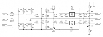
The alternating voltage after the transformer passes through 2 PTC fuses of 250 mA, to a diode bridge made of SF26 diodes, which in turn are shunted by 10 nF capacitors. Then the voltage goes to filtering capacitors C24, C25, 2200 uF each, whichshunted by 100 nF capacitors. From these filter capacitors, the voltage goes to active smoothing filters, which are called capacitance multipliers. These active smoothing filters consist of Darlington transistors VT1, VT2, resistors R13, R14, R15, R16 and capacitors C20, C21. Further, the voltage after the filter goes to 2 integrated stabilizers LM7812 / LM7912, included according to the standard circuit from the datasheet. I must also add that this capacitance multiplier adds a soft start that prevents popping in the speakers when the pre-amplifier is turned on.
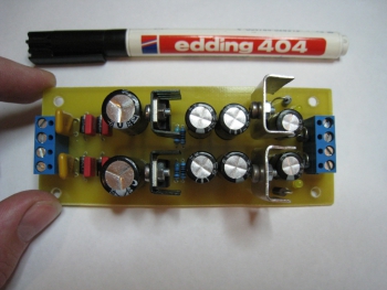
The board turned out to be miniature, below is a photo:
The input selector that should have beento carry out switching from several signal sources, made in a simple way. Since I do not need more than 2 inputs, I limited myself to one signal relay, which has 2 groups of "NC", "NO" contacts. Thus, by default, the preamplifier was connected to the computer, and when the relay was turned on, it was connected to a free pair of RCA connectors. To which it was possible to connect something else. When I started doing it printed circuit board, I decided to add a 12 volt stabilizer there, so as not to make another small board.
This scarf came out:
Unfortunately, I did not find angular RCA connectors for the board. So I bought regular RCAconnectors, below photo:
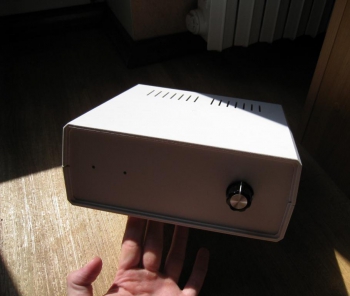
Secured these RCA connectors in the case. With the case, I decided not to suffer too much, but to buy a ready-made one. The case, of the size that I needed, alas, was not, I took the one that was more or less suitable. If the body were slightly lower in height, it would be ideal. But oh well, after fixing it into the case, everything began to look like this:
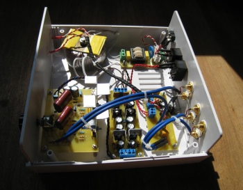
I used a high-quality shielded wire, with a rather thick braid, in the signal circuits, this is the one that is blue in the photo. Because when I connected the input / output with ordinary copper, twisted wire, there was not a lot of hum. Also, the case took a little more, in width, in order to place the transformer away from everything "signal". In this case, the toroidal transformer is located at a distance of 90 mm from the board, the preamplifier. And I connected this transformer through a surge protector, purely for the sake of reinsurance. In catfish surge protector no, nothing special, the same as I did in my amplifier.There are 2 capacitors of 47 nF each, a Murata common mode choke and an Epcos 391 varistor.To be honest, I was most afraid of the drone, but personally, the network drone visited me only when not connected all the RCA connectors ground together (I forgot it corny), and used an unshielded wire in the signal circuits. But in any case, the background is not working now, which is glad :)
Some photos:
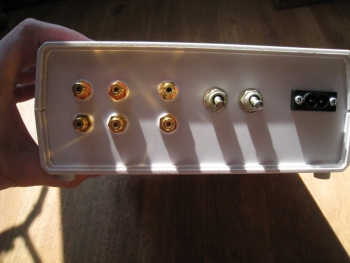
Installed on the back panel 2 pairs RCA inputs, RCA output, power switch, input switch, figure-of-eight network connector.
Here you can see what is the distance from the transformer to the boards.
On the front panel there is a volume control, 2 indication LEDs. One power supply, the second switch input.
After listening to this pre-amplifier, with my amplifier on the LM1875, I was pleased. The sound has become more pleasant, softer, perhaps the effect of field-effect transistors :) Now there was an idea, to assemble an external DAC, in order to raise music playback from a computer to a notch.
List of radioelements
| Designation | Type of | Denomination | Quantity | Note | Shop | My notebook | |
|---|---|---|---|---|---|---|---|
| Amplifier circuit. | |||||||
| VT1, VT2 | MOSFET transistor | IRF540N | 2 | Search LCSC | Into notepad | ||
| VT3 | Bipolar transistor | 2N5551 | 1 | Search LCSC | Into notepad | ||
| C2 | Capacitor | 2.2-4.7 uF | 1 | Search LCSC | Into notepad | ||
| C3, C4 | Capacitor | 20 pF | 2 | Search LCSC | Into notepad | ||
| C5, C7 | Capacitor | 0.1 uF | 2 | Search LCSC | Into notepad | ||
| C6, C8 | Electrolytic capacitor | 470 uF | 2 | Search LCSC | Into notepad | ||
| R1 | Resistor | 100 ohm | 1 | Search LCSC | Into notepad | ||
| R2 | Resistor | 100 kΩ | 1 | Search LCSC | Into notepad | ||
| R3 | Resistor | 39 Ohm | 1 | Search LCSC | Into notepad | ||
| R4, R5 | Resistor | 470 Ohm | 2 | Search LCSC | Into notepad | ||
| R6 | Resistor | 390 Ohm | 1 | Search LCSC | Into notepad | ||
| R7 | Resistor | 10 kΩ | 1 | Search LCSC | Into notepad | ||
| R8 | Resistor | 1 MOhm | 1 | Search LCSC | Into notepad | ||
| R9 | Variable resistor | 100 kΩ | 1 | Search LCSC | Into notepad | ||
| Power supply circuit. | |||||||
| VR1 | Linear regulator | LM7812 | 1 | Search LCSC | Into notepad | ||
| VR2 | Linear regulator | LM7912 | 1 | Search LCSC | Into notepad | ||
| VT1 | Bipolar transistor | TIP127 | 1 | Search LCSC | Into notepad | ||
| VT2 | Bipolar transistor | TIP122 | 1 | Search LCSC | Into notepad | ||
| VD1, VD2 | Rectifier diode | SF26 | 8 | Search LCSC | Into notepad | ||
| HL1, HL2 | Light-emitting diode | 2 | |||||
Part 1 . Blocks of VHF devices. Article 2. LF amplifier blocks.
Amplifiers of power AF.
Amateur designs of various options for LF power amplifiers can be found in any amateur radio reference book and magazines such as Radio, Radiomir. KB and VHF "," Radio amateur "," Radioconstructor "and many others. So the radio amateur has a huge selection of ULFs for every taste. In this article, I will give descriptions of those constructions that I myself have tested and used in practice.
When choosing an amplifier circuit, it should be remembered that high-quality ULFs with a huge bandwidth of audio frequencies are not needed at all for amateur radio stations. For a communication receiver, the required bandwidth of the LF signals lies in the range of 300 ... 3000 Hertz. This band is quite enough for both high-quality reception of signals by human hearing organs and for the operation of devices. digital communication.
All frequencies above or below the specified range will only cause harm. Therefore, a low-pass filter must be installed at the input of the amplifier. In addition, the amplification of high frequencies can be damped by the selection of correction capacitors and resistors. You can significantly increase the sensitivity of the ULF by increasing the resistance R2 to 120 ohms.
ULF on m / sh K174UN7
Chips of the K174 series provide the radio amateur with a large selection of different radio designs. K174UN7 is a bass amplifier with the following parameters:
Supply voltage 15 V;
Rated output power 4.5 W;
Harmonic distortion for output power 0.05 W - 2%, for 4.5 W - 10%;
Frequency band from 40 to 20,000 Hz;
Input impedance 50 kOhm;
Load resistance 4 Ohm;
Gain 40 dB;
The maximum peak value of the current in the load is 1.75 A;
The maximum peak value of the output voltage is 2 V;
The allowed DC voltage at pin 7 is 15 V;
Permissible constant voltage at pin 8 from minus 0.3 to 2 V;
It is unacceptable to apply external DC voltage to terminals 5, 6, 12.
The microcircuit must be placed on a heat sink - cooler.
In fig. 2.1 is given circuit diagram ULF, made on the K174UN7 microcircuit.
This amplifier has a wide audio bandwidth. Therefore, a low-pass filter must be installed at the amplifier output. In addition, it is fashionable to extinguish the amplification of high frequencies by selecting correcting capacitors and resistors. You can significantly increase the sensitivity of the ULF by increasing the resistance R2 to 120 ohms.
The amplifier practically does not require any setup. Subsequently, after the complete manufacture of the entire radio receiver with this ULF, it will be possible to try to change the output frequency response selection of the values of correcting capacitors and resistors (if necessary!).
In the K174 series there are other LF amplifier microcircuits suitable for communication equipment.
ULF on transistors - option 1.
For those who like to work with old brands of transistors, here is a proven circuit. simple ULF on transistors, shown in Fig. 2.2.
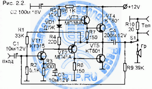
The input sensitivity of the amplifier is approximately 0.25V, so for its normal work as part of the radio receiver, it is required to install another LF amplifier between the detector and this amplifier, the so-called "preliminary ULF", which should amplify the signals received from the detector to a value of 0.25V.
The output power of the amplifier is about 2 W, the harmonic distortion is not more than 3%, the output should be a loudspeaker with a coil resistance of 5 ... 8 Ohm.
The stabilization of the output stage mode is carried out using the VD1 diode. The diode should be selected according to the criterion of obtaining as little distortion as possible with a small signal at the input. You can try diodes D18, D310 and others, while remembering an indispensable requirement: the diode can be replaced only when the power is off.
The amplifier can operate at a lower supply voltage. With a supply voltage of 9V and a speaker impedance of 8 ohms, the output power will be approximately 1 W, and with a supply voltage of 6V, approximately 0.5 W
The adjustment is carried out by selecting the resistors R1 and R9 so that the voltage at the positive electrode of the capacitor C4 is equal to half the supply voltage. In this case, the value of the current in the silence mode through the transistors VT4 and VT5 should be within 2 ... 3 mA.
In a similar scheme, you can make ULF and modern transistors.
ULF on transistors - option 2.
In fig. 2.3 shows a schematic diagram of another version of the transistor ULF. This circuit is similar to the ULF circuit in the design of the base receiver of the KB radio station developed by Ya. S. Lapovk. In this circuit, in comparison with the analogue, other transistors are used.
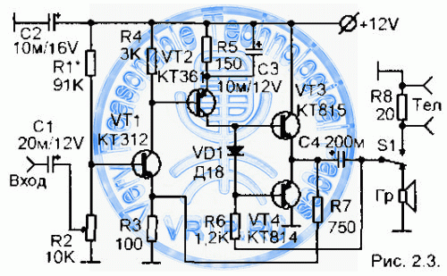
Setting the ULF consists in selecting the resistance R1 to such a value that on the positive electrode of the capacitor C4 (at the common point for transistors VT3 and VT4) the voltage value is half of the supply voltage. Also, like the previous ULF, this amplifier needs an additional (pre) amplifier.
Preamplifiers LF. Transistor preamplifier.
In household radios, pre-low frequency amplifiers are usually supplemented with audio frequency correction functions. In radio receivers for communication, there is no need for such a correction, because the range of the reproduced ULF of the communication receiver should not go beyond the range of 300 ... 3000 Hz. Therefore, pre-amplifier circuits can be very simple. In fig. 2.4 shows a diagram of a simple, but quite effective transistor LF preamplifier in operation. The circuit is presented in two versions, which differ only in the structure of the applied transistors.
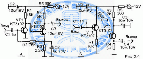
Setting the ULF consists in selecting the resistance R2 to a value at which in the silent mode the voltage drop across the resistor R4 will be exactly half of the supply voltage. In other words, the voltage at the collector of the transistor VT2 should be equal to half the supply voltage.
Preliminary ULF on microcircuits.
As a rule, the developer of a new radio receiver seeks to distribute the total gain between its stages in such a way that the greatest share of the gain falls on the IF and ULF amplifiers. Therefore, the desire of the radio designer to create an ULF with the maximum possible gain is understandable. A similar problem can be solved with the help of low-frequency preamplifiers, made on operational amplifiers. In fig. 2.5 shows one of the possible LF preamplifier circuits based on an operational amplifier of the K140UD6 type. You can also use K140UD7, K140UD12 and others.
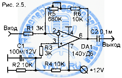
The gain shown in Fig. 2.5 amplifier is equal to the ratio of the sum of the values (R5 + R6) to the value of the resistance of the resistor R1. For example, if the total value of the resistances R5 and R6 is 50 ohms, and the resistance value of the resistor R1 is 10 ohms, then the gain will be 10.
Tuning the amplifier consists in selecting the most convenient value for the resistance of the variable resistor R5. Strictly speaking, a variable resistor is not needed here. The selection can be carried out with various fixed resistors.
In fig. 2.6 shows a diagram of a pre-amplifier on a K548UN1 microcircuit. This microcircuit is two identical low-noise ULF.
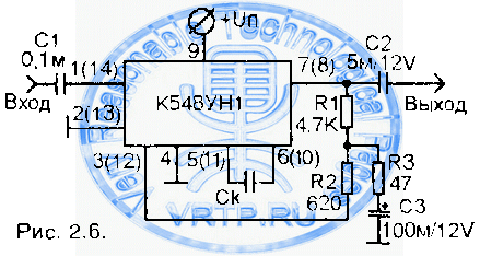
The amplifier parameters depend on the OOS depth, which is determined by the ratio of the resistances of the resistors R1 and R3. With the resistance values indicated in the diagram, the amplifier is characterized by the following parameters:
Voltage amplification factor 100 (equal to the ratio of resistances R1 / R3),
Input impedance is 300 kOhm,
Output - no more than 1 Ohm,
The highest operating frequency is not less than 100 kHz.,
Harmonic distortion at a frequency of 1 kHz with a load resistance of 10 kOhm no more than 0.05%,
Noise figure (measured in a frequency band up to 23 kHz with a signal source resistance of 10 kΩ) no more than 2.
If the voltage gain is increased to 1000, the highest operating frequency is reduced to about 20 kHz. and the harmonic distortion rises to 0.1%. Correction capacitor C is included if necessary to limit the operating frequency range. The pins shown in brackets of the microcircuit refer to the second amplifier located in the same package.
Combined ULF option
In fig. 2.7 depicts the principal electrical circuit LF amplifier, which includes a pre-amplifier based on an operational amplifier K140UD6 and a power amplifier based on 5 transistors. A feature of the transistor power amplifier is that this amplifier is designed to operate in class AB mode, which is characterized by low linear distortion.
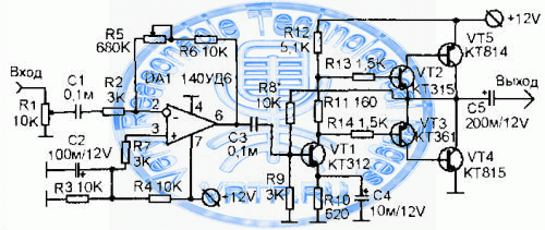
With the values of radio components indicated on the diagram. ULF provides an output power of about 1 W and has an efficiency. about 60%. The input resistance is about 300 Ohm, the output resistance is 10 ... 20 Ohm. The transistor power amplifier is adjusted by selecting the resistance R8 to such a value at which the voltage at the junction point of the collectors of transistors VT4 and VT5 will become equal (in silence mode) to exactly half the supply voltage.
The op-amp stage has no special features.
Low Pass Filters
As already mentioned when considering the block diagram of the receiver, after detection, it is necessary to clear the received signal from the side frequencies present in it, i.e. signal filtering is required. After detection, the signal will certainly contain both high (above 3000 Hz) and low (below 300 Hz) side results of detection and various interference, for example, with a frequency of 50 Hz from a power supply. By the way, with poor filtering, frequencies of both 100 Hz and 200 Hz can be induced from the power source - these are higher harmonics of the frequency electrical network 50 Hz.
It is necessary to filter the signal in the course of its conversion in the receiver several times, but here the circuits of low-frequency cascades are considered and it is the design of the band-pass low-pass filters that are subject to consideration.
The main filtering of the signal after detection should be carried out by low-pass filters (LPF). International standard sets the upper cutoff frequency of the telephone channel to 3400 Hz for good speech intelligibility. Improving the noise immunity and selectivity of receivers, amateurs are content with a narrower band with an upper cutoff frequency of 2700 ... 3000 Hz.
The simplest low-pass filter, installed at the output of the detector or the last (telegraph) mixer of the receiver or transceiver, it is advisable to perform on LC elements according to the so-called U-shaped scheme in Fig. 2.8.
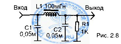
In my opinion, this is the most effective of these filters and can be successfully applied even in receivers. direct conversion... Its loss is negligible, with a selectivity of 23 dB at twice the cutoff frequency, and 32 dB at three times the cutoff frequency. For large detunings, it is 60 dB per decade (tenfold increase in frequency). The relationships between the filter elements are determined by the formulas: C1 = C2 = 1 / (2 * π * fc * R), L1 = R / (π * fc), where fc is the cutoff frequency, n is pi = 3.14. Resistance R1 is usually the ULF input impedance. It is sufficient to maintain the L and C values with an accuracy of 10%; therefore, the filter does not require adjustment.
V.T.Polyakov, author of the book "Broadcast FM receivers with phase-locked loop", recommends creating a slight rise in the high frequencies of the audio spectrum. He believes that such a rise is useful for improving intelligibility, so it is advisable to calculate the filter for a resistance of 1.5 ... 2 times less than the real load. Typical values of elements for fc = 3 kHz are as follows: C1 = C2 = 0.05 μF, L1 = 0.1 H, R = 1 ... 2 kΩ.
The coil is wound on a K16x8x4 ring magnetic core made of 2000NM ferrite and contains 260 turns of any suitable insulated wire. The good thing about toroidal coils is that they are little susceptible to extraneous magnetic interference and most often do not require shielding.
The INDUKTIW program will help you to calculate any elements of the oscillatory circuit, which you can take on the Internet at the website at: http://r3xb-tga.narod.ru/ or http://r3xb.by.ru.
One of the windings of a miniature transformer from portable successors can also serve as the filter inductance; the primary winding of the output transformer is best suited.
There is usually no need to filter frequencies below 300 ... 400 Hz - this role is played by decoupling capacitors in the ULF, the capacitance of which is selected from the condition C = 1 / (2 * n * fn * R), where fn is the lower frequency of the sound spectrum, R is the input impedance of the stage following the blocking capacitor.
If you have this moment there is no suitable inductor, you can make an RC filter by replacing the coil with a 300 ... 800 ohm resistor. The filtering will be slightly worse, but the receiver's performance will remain. In some cases, the value of this resistor can be increased to 3 kΩ.
Instead of a conclusion.
In amateur radio practice, a huge number of a wide variety of schemes are used. Each of us uses those schemes that are more convenient for him due to the available set of parts, or for some other, only he understands reasons. In this series of articles, I will cite the schemes that I use in my practice. Some will like them, some will not. I don't think at all that the schemes I have chosen are the best. Surely there are more convenient circuits on modern radio components. Look for what you like.