A headphone amplifier circuit that definitely deserves attention. Here and the doubled output current and the absence of blocking capacitors in the signal path. At the same time, the headphone amplifier circuit is very simple and straightforward.
Updated : The input blocking capacitor has been removed from the circuit. The values of the input resistors have been changed.
Headphone amplifier circuit
Regular wanderings across endless spaces dumpsters a storehouse of knowledge - the Internet, led to an interesting find. It was a PDF from Burr Brown. Which inspired me to create an op amp headphone amplifier. From the language of a potential enemy, its name can be literally translated as follows: Doubling the output current into a load with two OPA2604 audio op amps .
The file consists of two pages, where only the first is valuable. The headphone amplifier circuit presented there has been redrawn and rid of unnecessary clever inscriptions.
Meet this is the future heart of our amplifier. To be more precise, this is a single channel scheme. We will have 2 channels, which means we need two dual operational amplifiers ( OU ).
Resistors R3 and R4 with a resistance of 51 ohms are needed to protect the outputs of the operational amplifiers.
What is the "trick" of this amplifier?
The scheme is not new at all, and is known from the datasheets of the 90s. But the interesting thing about the circuit is that both op amps amplify the same signal. But this is not a bridge connection. The output signals of both op amps are in phase, and their output currents are added.
Such inclusion solves the problem of low output current of many op amps. This significantly increases the number of op amps that can be used in an amplifier. It is now sufficient that each op-amp can supply 35-40 mA of output current, instead of 70-80 for one op amp per channel.
The maximum value of the output current is always given in the datasheet on the op-amp.
Gain
The signal gain is determined by the resistors R1 and R2 ... Its exact value is determined by the formula:
K = 1+ R2 / R1
If you focus on a linear output with a signal level of 1 Volt, then for most headphones a gain of three will be quite enough. We will equalize by three.
It is desirable that the resistors that set the gain have an accuracy not worse than ± 1% ... There are often not too many precision resistors available in stores. But in this case, you can get by with resistors of the same rating.
In the bins of the cabinet, precision resistors of 7.5 kOhm were found, which became a resistor R1 ... As R2 two 7.5 kΩ resistors were connected in series. The same can be done by connecting in parallel two 15 kOhm resistors as R1 , and one 15k ohm resistor as R2 .
To change the gain, it is better to change the resistor R2 ... For op-amp circuits, it is usually recommended to use resistors with a nominal value of 1 ÷ 100 kOhm. Resistor R1 will perform another important function, therefore preferably 7.5kΩ.
We bring the scheme to mind
The diagram presented in the document is somewhat incomplete and reflects only the most important thing. For normal operation, the circuit should be supplemented with input circuits, as well as parallel to the resistor R2 a small capacitor should be added. It is needed to exclude self-excitation of the op-amp.
For starters, let's not reinvent the wheel and borrow the input circuit from the headphone amplifier. FiiO Olympus E10. In this case, the circuit of our amplifier will take the following form:
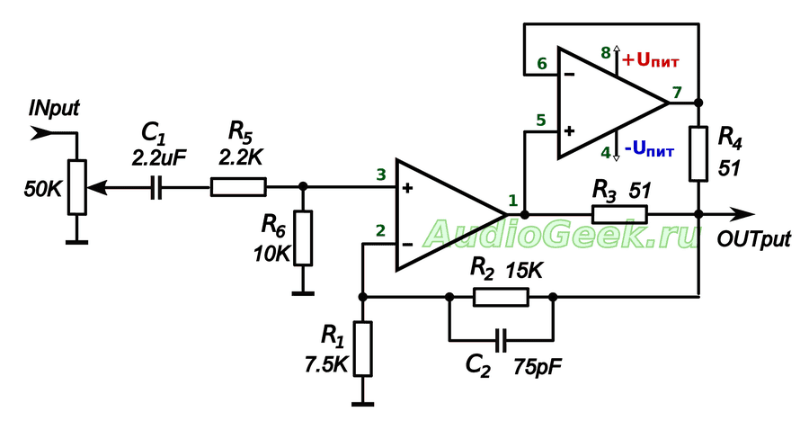
The diagram shows the legs for a dual operational amplifier in a DIP8 package. The scheme is completely working and does not need any adjustment.
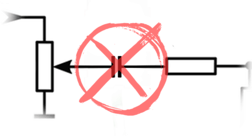
Let's throw out the capacitor from the input
The op-amp amplifies both AC and DC voltage equally well. Capacitor( C1 ) is needed in order to cut off the DC voltage at the input. On the one hand, normal signal sources do not provide a constant output. On the other hand, if it suddenly appears, then it needs to be cut off. And even the headphones can be burned.
But people actively do not want to see extra capacitors in the signal path, so we will get out.
Rereading once again " The art of circuitry Horowitz and Hill, found what he was looking for. To get an AC amplifier, you need to include a capacitor similar to C1 , in series with the resistor R1.
In this case, the feedback of the op-amp will work only on change and the need for a capacitor at the input will disappear. Therefore, you can safely move C1 from the input of the amplifier to the feedback circuit of the op-amp.
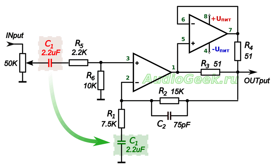
Formed ( R1 , C1 ) will cut off both DC voltage and infra-low frequencies ( <10Гц ). They do not carry useful information, but they significantly load the amplifier in terms of current.
Also, this inclusion of the capacitor will reduce the voltage of the op-amp unbalance at the inputs. And it, by the way, is also amplified and mixed into the output signal. In this case, the capacitor in the feedback circuit has practically no effect on the sound, in contrast to the capacitor at the input. In general, some poles from such a permutation.
Input resistors
Removing the capacitor from the input forced a closer look at the resistors R5 and R6, remaining at the entrance. And why are they needed at all and how to calculate them?
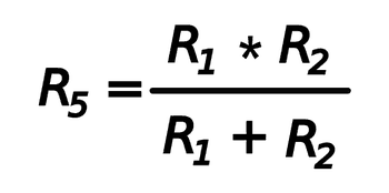
Resistor R5 called compensating and is necessary to ensure equal resistance between each of the inputs and ground. Its value is defined as the parallel resistance of the resistors R1 and R2 .
However, we have consistently with R1 there is a capacitor C1. The resistance of the capacitor depends on the frequency and is added to the resistance of the resistor. The resistance of a capacitor at a certain frequency is determined from the ratio:
R С = 1 / (2 × π × F × C),
Where F in Gegrtsy, WITH in Farads, and R C in Omah
To determine resistance R5, first, the values of the resistances of a 2.2 μF capacitor were calculated at frequencies of 20 Hz and 20 kHz. Then, for both cases, the values of the compensating resistors were calculated. It turned out that the resistance of the resistor R5 should lie between 8.91 k Ohm (for 20 Hz) and 6.81 k Ohm (for 20kHz). Without hesitation stuck 7.5 kΩ.
With a capacitor, we decoupled the inverting input of the amplifier from the DC ground. But the op-amp must be connected to ground in both AC and DC. This is what the resistor is for. R6 ... Its value was chosen equal to 75 kOhm. But you can also put 100 kOhm. Less than 75 kOhm, with a variable change of 50 kOhm, I would not recommend setting it. Together with a resistor R5 they will begin to bypass the input variable resistor.
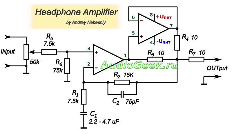
In the diagram, the output was also slightly changed. The values of R3 and R4 were reduced to 10 ohms, and a resistor R7 with the same resistance was connected in series with them. This should provide a better summation of the output signals.
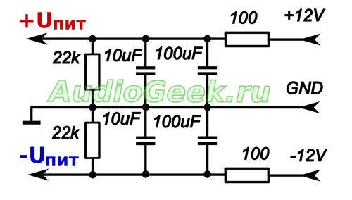
Amplifier supply
The quality of the food is very important for the sound. This circuit is designed for a bipolar supply voltage. This saves us the trouble of adding extra detail to the audio path, and is generally better for sound.
Op-amps exist today that operate from ± 1.5V, but most opamps operate on a bipolar supply voltage of ± 3V to ± 18V. The optimal voltage can be called ± 12V, which is included in the supply range of most op amps.
The exact values of the maximum supply voltage should be found in the documentation for specific microcircuits.
Component quality
It is not necessary to immediately purchase expensive parts. To begin with, you can put something from the assortment of the nearest radio parts store, and gradually replace them with better components. The board will work on any details.
Capacitor C1 must be non-polar. Better polypropylene or film. It is better to use a ceramic capacitor C2. The accuracy of the capacitors is not very important. but it is better to use it with an accuracy of at least 5%.
Op-amp prices vary widely and doesn't always mean better for sound. To begin with, you can install something inexpensive and affordable, for example, the beloved NE5532 ($ 0.3). It is highly desirable that it be produced by Phillips.
Subsequently, with the replacement of the op-amp, you can play as much as you want. If we consider the op-amp as a higher class, then OPA2134, OPA2132, OPA2406, AD8066, AD823, AD8397 ... have proven themselves well for sound.
I do not recommend ordering microcircuits from Aliexpress and other Chinese stores. There are quite a few reviews in which people report that the microcircuits are not original. Yes, the op-amp will work as it should, but it may not be the OPA2134 you ordered at all, but a rather cheap TL061 labeled OPA2134 ...
Conclusion
The resulting amplifier circuit, assembled on the OPA2132 and operating even at a supply voltage of ± 5V, freely shakes the rather tight Sennheiser HD380 Pro.
I do not like to describe the sound in subjective terms like "highs became crystal" or "bass warm", I can only say that when using a good op-amp, this headphone amplifier has a sufficient margin of volume and output power. At the same time, it does not require any tuning and uses a minimum of details, while providing decent sound quality.
The considered scheme led to the idea of creating a portable headphone amplifier. So came up with ... The essence of which is to create a complete design of a portable headphone amplifier with your own hands from scratch.
Material prepared exclusively for the site


