Power supply diagrams
Excessive output current in power supplies indicates an increase in power consumption in the load device. Sometimes the current consumption in the load (due to a malfunction of the connections or the load device itself) can increase up to the value of the short-circuit current (short circuit), which will inevitably lead to an accident (if the power supply is not equipped with an overload protection unit).
The consequences of overloading may turn out to be more significant and irreparable if you use a power source without a protection unit (as radio amateurs often do today, making simple sources and buying inexpensive adapters) - power consumption will increase, the network transformer will fail, individual elements may ignite and an unpleasant smell.
In order to notice in time that the power supply is in a "normal" mode, simple overload indicators are installed. Simple ones, because they usually contain only a few elements, inexpensive and affordable, and these indicators can be installed universally in almost any home-made or industrial power supply.
Simple overcurrent indicator circuit
The operation of its elements is based on the fact that a limiting resistor of low resistance (R3 in the diagram) is connected in series with the load in the output circuit of the power supply.
This unit can be used universally in power supplies and stabilizers with different output voltages (tested under conditions of 5-20 V output voltage). However, the values and ratings of the elements indicated in the diagram in Fig. 3.4, matched to a 12V power supply.
Accordingly, in order to expand the range of power supplies for this design, in the output stage of which the proposed indication unit will work effectively, it will be necessary to change the parameters of the elements R1-R3, VD1, VD2.
As long as there is no overload, the power supply and the load node are operating normally, a permissible current flows through R3 and the voltage drop across the resistor is small (less than 1 V). Also, in this case, the voltage drop across the diodes VD1, VD2 is small, while the HL1 LED barely glows.
With an increase in the current consumption in the load device or a short circuit between points A and B, the current in the circuit increases, the voltage drop across the resistor R3 can reach its maximum value (output voltage of the power supply), as a result of which the HL1 LED will light up (will blink) in full force.
For a visual effect, a flashing LED L36B is used in the circuit. Instead of the indicated LED, you can use devices similar in electrical characteristics, for example, L56B, L456B (high brightness), L816BRC-B, L769BGR, TLBR5410 or the like.
The power dissipated on the resistor R3 (at a current short-circuit) is more than 5 W, therefore this resistor is made independently from copper wire of the PEL-1 (PEL-2) type with a diameter of 0.8 mm.
It is taken from an unnecessary transformer. 8 turns of this wire are wound onto the frame made of a clerical pencil, the ends of it are tinned, then the frame is removed. The wirewound resistor R3 is ready.
All fixed resistors of MLT-0.25 type or similar. Instead of diodes VD1, VD2, you can install KD503, KD509, KD521 with any letter index. These diodes protect the LED in overload mode (extinguish excess voltage).
Overload indicator with audible and visual alarm
Unfortunately, in practice, it is not possible to constantly visually monitor the state of the indicator LED in the power supply, so it is reasonable to supplement the circuit with an electronic sound unit. Such a scheme is shown in Fig. 2.
As can be seen from the diagram, it works on the same principle, but unlike the previous one, this device is more sensitive and the nature of its operation is due to the opening of the transistor VT1, when the potential in its base is more than 0.3 V. A current amplifier is implemented on the transistor VT1.
The transistor is selected with germanium. From the old stocks of the radio amateur. It can be replaced with devices similar in electrical characteristics: MP 16, MP39-MP42 with any letter index. In extreme cases, you can install a silicon transistor KT361 or KTZ107 with any letter index, but then the threshold for turning on the indication will be different.
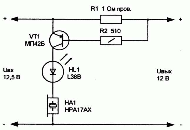
The threshold for turning on the transistor VT1 depends on the resistance of the resistors R1 and R2, and in this circuit, at a power supply voltage of 12.5 V, the indication will turn on at a load current exceeding 400 mA.
In the collector circuit of the transistor, a blinking LED and a capsule with a built-in AF generator HA1 are included. When the voltage drop across the resistor R1 reaches 0.5 ... 0.6 V, the VT1 transistor will open, the supply voltage will be sent to the HL1 LED and the HA1 capsule.
Since the LED capsule is an active current limiting element, the LED operating mode is normal. Thanks to the use of the flashing LED, the capsule will also sound intermittently - the sound will be heard during the pause between LED flashes.
In this circuit, an even more interesting sound effect can be achieved if, instead of the HA1 capsule, you turn on the KRI-4332-12 device, which has a built-in generator with interruption. Thus, in the event of an overload, the sound will resemble a siren (this is facilitated by a combination of interrupts of LED flashes and internal interrupts of the HA1 capsule).
Such a sound is quite loud (audible in the next room with an average noise level), it will definitely attract the attention of people.
Blown fuse indicator
Another diagram of the overload indicator is shown in Fig. 3. In those designs where a fusible (or other, for example, self-resetting) fuse is installed, it is often required to visually monitor their operation.
It uses a two-color LED with a common cathode and, accordingly, three leads. Those who have tested these diodes with one common terminal in practice know that they function somewhat differently than expected.
The thinking pattern is that it would seem that green and red colors will appear in an LED in a common case, respectively, when a voltage is applied (in the correct polarity) to the corresponding terminals R or G. However, this is not entirely true.
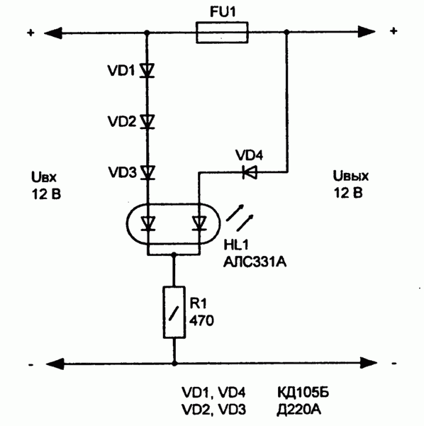
While fuse FU1 is good, voltage is applied to both anodes of LED HL1. The glow threshold is adjusted by the resistance of the resistor R1. If the fuse breaks the power supply circuit of the load, the green LED goes out, and the red one stays on (if the supply voltage has not disappeared at all).
Since the permissible reverse voltage for LEDs is small and limited, for this design, diodes with different electrical characteristics VD1-VD4 are introduced into the circuit. The fact that only one diode is connected in series to the green LED, and three to the red one, is explained by the features of the ALC331A LED, seen in practice.
In experiments, it turned out that the threshold of the voltage for turning on the red LED is less than that of the green one. To balance this difference (only noticeable in practice), the number of diodes is not the same.
If the fuse blows, voltage is applied to the green LED (G) in reverse polarity.
The ratings of the elements in the circuit are given for monitoring the voltage in the 12 V circuit. Instead of the ALC331A LED, it is permissible to use other similar devices, for example, KIPD18V-M, L239EGW.


