Now you will learn how to turn an ordinary dial (analog) voltmeter into a digital thermometer using the Arduino platform and a ds18b20 temperature sensor. In principle, this technology is suitable not only for displaying temperature - any other (physical and electrical) values from different sensors can be digitally displayed on a dial gauge using this method.
DS18B20 module
The well-known ready-made module ds18b20 is a digital thermometer that provides 9-bit temperature measurement and has a non-volatile programmable upper and lower operating point function. In addition, the ds18b20 communicates over the 1-Wire bus and requires only one data line to communicate with the microprocessor. In addition, the ds18b20 can be powered directly from the data line, eliminating the need for an external power supply.
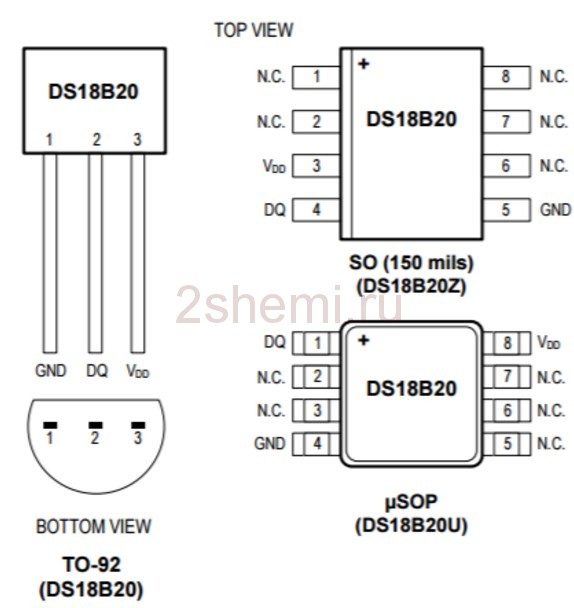 ds18b20 pinout
 In fact, each ds18b20 has a unique 64-bit serial code that allows even multiple DS18B20s to function on the same 1-Wire bus. Thus, using just one microprocessor, it is possible to monitor many temperature sensors distributed over a large area.
Thermometer assembly diagram
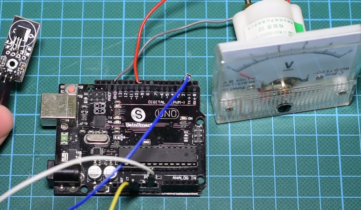 Connecting elements to the board
 The circuit itself is so simple that there is no point in drawing it - all connections are visible in the photograph. First, connect ds18b20 to pin (-) for Arduino ground, pin (+) for 5V and signal output to digital pin 2.In order to control the voltmeter, connect its positive wire to pin 9 (one of the PWM) and connect minus to GND. After that, to change the scale on the voltmeter to a thermometer, just print out the photo that is attached to the article. The voltmeter is 5 V here, but you can take any other indicator, including a regular microammeter, by adding the required resistor in series to it (about 10-100 kOhm).
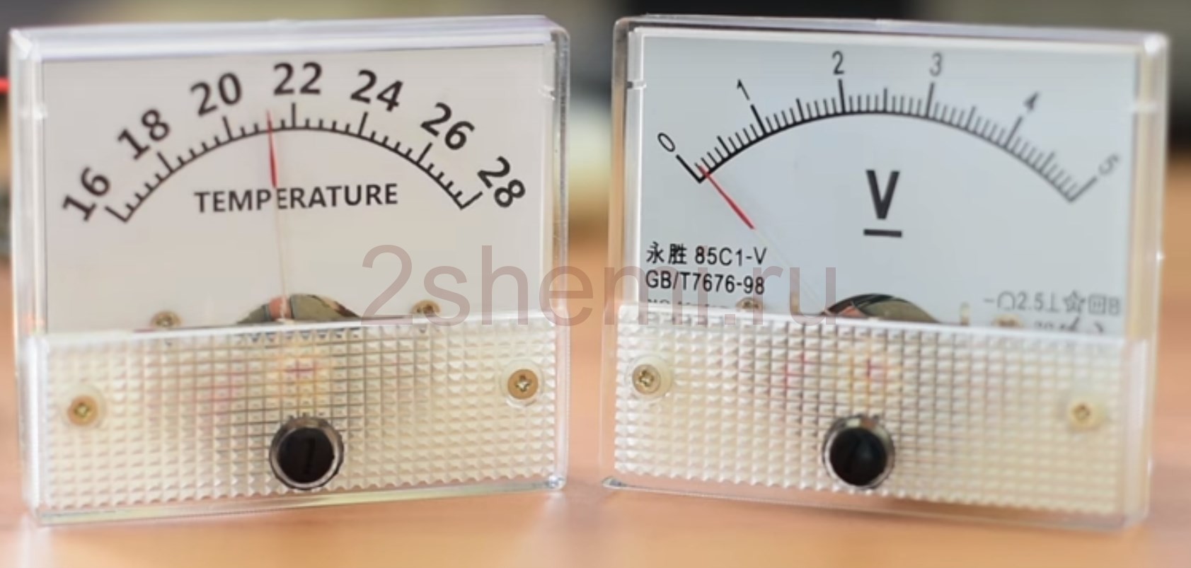 Pointer thermometer and voltmeter
 List of required parts
- Arduino Uno
- DS18b20 sensor
- Pointer voltmeter
- Multiple wires
- Power supply (can be battery)
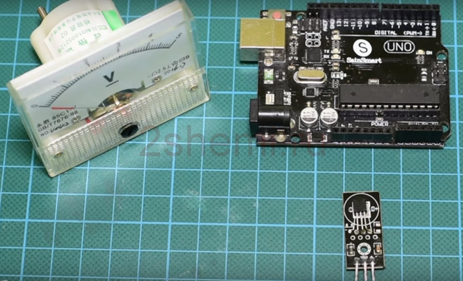 Thermometer parts
 Principle of operation
Pulse Width Modulation, or PWM, is a technique for obtaining analog results using digital means.
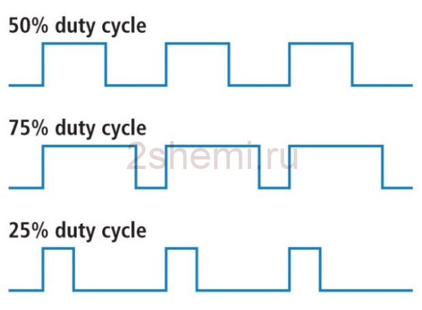 Pulse width modulation switch control
 When flashing the microcontroller, you must add the “DallasTemperature library” to your Arduino development environment, as this is the library that supports the ds18b20 temperature sensor.
The code has three main parts:
- Reading the temperature from the sensor
- Converting temperature to PWM
- Displaying the value on the scale
Thermometer setting
In the settings, we will read the temperature from the sensor. Then, we convert this value to a PWM function in the range 0 to 255. This can be done inside a program function. Next, let's apply a signal to pin 9, which is connected to a dial-up voltmeter.
When setting the temperature range, keep in mind that the smaller the gap between the extreme values, the greater the thermometer's resolution. You can download the datasheet for the sensor and the firmware code.


