Amplifier design has always been a challenge. Fortunately, in recent years, there have been many integrated solutions that make life easier for amateur designers. I, too, did not complicate the task for myself and chose the simplest, high-quality, with a small amount of details, does not require tuning and stably operating amplifier on the TDA7294 chip from SGS-THOMSON MICROELECTRONICS. Recently, on the Internet, I spread and read and saw complaints about this microcircuit, which were expressed approximately in the following: "spontaneously excited, with incorrect wiring; burns, for any reason, etc.". Nothing like this. You can burn it only by incorrect switching on or closing, and cases of excitement have not been noticed even once, and not only with me. In addition, it has an internal load short-circuit protection and overheating protection. It also has a muting function (used to prevent clicks when turned on) and a standby function (when there is no signal). This IC is a class AB ULF. One of the main features of this microcircuit is the use of field-effect transistors in the preliminary and output amplification stages. Its advantages include high output power (up to 100 W at a load of 4 ohms), the ability to operate in a wide range of supply voltages, high technical characteristics (low distortion, low noise level, a wide range of operating frequencies, etc.), the minimum required external components and low cost
Main characteristics of TDA7294:
|
Parameter |
Conditions |
Minimum |
Typical | Maximum | Units |
| Supply voltage | ± 10 | ± 40 | IN | ||
| Frequency Response Range | signal 3db Output power 1W |
20-20000 | Hz | ||
| Long Term Output Power (RMS) | harmonic coefficient 0.5%: Uп = ± 35 V, Rн = 8 Ohm Uп = ± 31 V, Rн = 6 Ohm Uп = ± 27 V, Rн = 4 Ohm |
60 60 60 |
70 70 70 |
W | |
| Peak music output power (RMS), duration 1 sec. | harmonic coefficient 10%: Uп = ± 38 V, Rн = 8 Ohm Uп = ± 33 V, Rн = 6 Ohm Uп = ± 29 V, Rн = 4 Ohm |
100 100 100 |
W | ||
| Total harmonic distortion | Po = 5W; 1kHz Po = 0.1-50W; 20-20000Hz |
0,005 | 0,1 |
% | |
| Uп = ± 27 V, Rн = 4 Ohm: Po = 5W; 1kHz Po = 0.1-50W; 20-20000Hz |
0,01 |
% | |||
| Protection response temperature | 145 | 0 C | |||
| Quiescent current | 20 | 30 | 60 | mA | |
| Input impedance | 100 | kOhm | |||
| Voltage gain | 24 | 30 | 40 | dB | |
| Peak output current | 10 | BUT | |||
| Working temperature range | 0 | 70 | 0 C | ||
| Thermal resistance of the case | 1,5 | 0 C / W | |||
Typical connection schemes:
List of elements:
| Position | Name | A type | Quantity |
| C1 | 0.47 uF | K73-17 | 1 |
| C2, C4, C5, C10 | 22 μF x 50 V | K50-35 | 4 |
| C3 | 100 pF | 1 | |
| C6, C7 | 220 μF x 50 V | K50-35 | 2 |
| C8, C9 | 0.1 uF | K73-17 | 2 |
| DA1 | TDA7294 | 1 | |
| R1 | 680 Ohm | MLT-0.25 | 1 |
| R2 ... R4 | 22 k Ohm | MLT-0.25 | 3 |
| R5 | 10 kΩ | MLT-0.25 | 1 |
| R6 | 47 k Ohm | MLT-0.25 | 1 |
| R7 | 15 kΩ | MLT-0.25 | 1 |
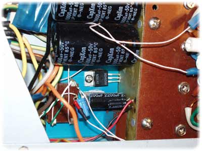
The microcircuit must be installed on a radiator with an area> 600 cm 2. Be careful, there is not a common, but a minus power supply on the microcircuit case! When installing the microcircuit on a radiator, it is better to use thermal grease. It is advisable to lay a dielectric (mica, for example) between the microcircuit and the radiator. The first time I did not attach any importance to this, I thought, why would I be so scared to close the radiator to the case, but in the process of debugging the structure, the tweezers that accidentally fell from the table closed the radiator to the case. The explosion was great! The microcircuits were simply blown to pieces! In general, I got off with a slight fright and $ 10 :). On a board with an amplifier, it is also advisable to supply powerful electrolytes of 10000mk x 50V to power, so that at power peaks, the wires from the power supply do not give voltage drops. In general, the larger the capacity of the capacitors on the power supply, the better, as they say, "you can't spoil the porridge with butter." Capacitor C3 can be removed (or not installed), that's what I did. As it turned out, it was because of him that when the volume control (a simple variable resistor) was turned on in front of the amplifier, an RC chain was obtained, which, with increasing volume, mowed high frequencies, but in general it is needed to prevent the excitation of the amplifier when ultrasound is applied to the input. Instead of C6, C7, I put 10000mk x 50v on the board, C8, C9, you can put any close value - these are power filters, they can be in the power supply, or you can solder them by hanging installation, which I did.
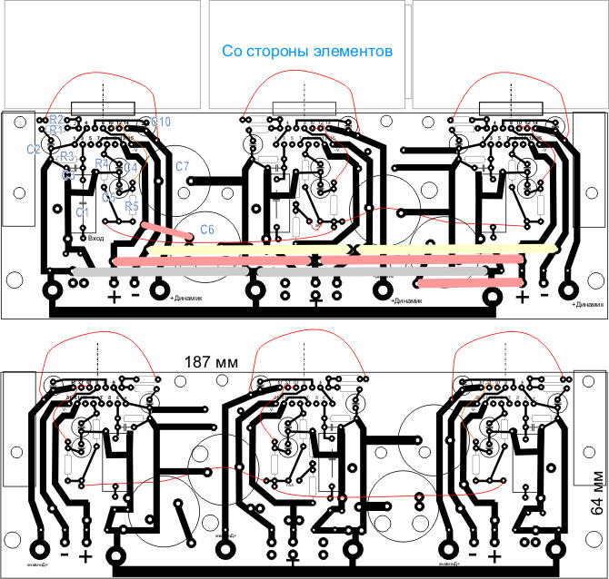
Pay:
I personally do not really like to use ready-made boards, for one simple reason - it is difficult to find exactly the same size elements. But in an amplifier, wiring can greatly affect sound quality, so it's up to you which board to choose. Since I assembled an amplifier for 5-6 channels at once, respectively, a board for 3 channels at once:
For some reason, the amplifier's power supply raises many questions. In fact, it’s just there, everything is quite simple. The transformer, diode bridge and capacitors are the main elements of the power supply. This is enough to assemble the simplest power supply.
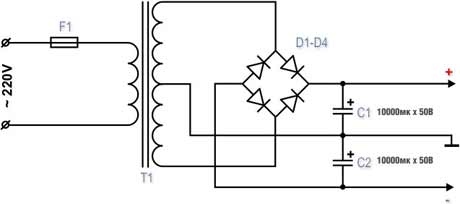
For powering a power amplifier, voltage stabilization is not important, and the capacitance of the capacitors for power supply is important, the more, the better. The thickness of the wires from the power supply to the amplifier is also important.
My power supply is implemented as follows:
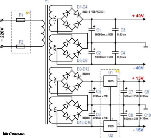
+ -15V power supply is intended for power supply of operational amplifiers in the amplifier preliminary stages. You can do without additional windings and diode bridges by powering the stabilization module from 40V, but the stabilizer will have to extinguish a very large voltage drop, which will lead to significant heating of the stabilizer microcircuits. Stabilizer chips 7805/7905 are imported analogs of our KREN.
Variations of blocks A1 and A2 are possible:
![]()
Block A1 is a filter to suppress power noise.
Block A2 - block of stabilized voltages + -15V. The first alternative is easy to implement, for powering low-current sources, the second is a high-quality stabilizer, but requires accurate selection of components (resistors), otherwise you will get a skew of the "+" and "-" arms, which will then give a skew of zero on the operational amplifiers.
TransformerThe power supply transformer for a 100W stereo amplifier should be about 200W. Since I was making a 5-channel amplifier, I needed a more powerful transformer. But I didn’t have to pump out all 100Watts, and all channels can’t take power at the same time. I came across a TESLA transformer (below in the photo) on the market for 250 watts - 4 windings with a wire of 1.5 mm at 17V and 4 windings at 6.3V. By connecting them in series, I got the necessary voltages, although I had to rewind two 17V windings a little in order to get the total voltage of the two windings ~ 27-30V, since the windings were on top - it was not difficult.
A great thing is a toroidal transformer, these are used to power halogen lamps in lamps, there are a lot of them in markets and shops. If constructively put two such transformers one on top of the other, the radiation will be mutually compensated, which will reduce the pickup on the amplifier elements. The trouble is that they have one 12V winding. On our radio market, you can make such a transformer to order, but this pleasure will be worth it. In principle, you can buy 2 transformers for 100-150 Watts and rewind the secondary windings, the number of turns of the secondary winding will need to be increased by about 2-2.4 times.
Diodes / diode bridgesYou can buy imported diode assemblies with a current of 8-12A, this greatly simplifies the design. I used pulse diodes KD 213, and I did it separately along the bridge for each arm to give a current margin for the diodes. When turned on, powerful capacitors are charged, the current surge is very significant, at a voltage of 40 V and a capacity of 10,000 μF, the charging current of such a capacitor is ~ 10 A, respectively, along two arms 20A. In this case, the transformer and rectifier diodes operate for a short time in short-circuit mode. Breakdown of diodes by current will give unpleasant consequences. The diodes were installed on the radiators, but I did not detect the heating of the diodes themselves - the radiators were cold. To eliminate power supply interference, it is recommended to install a capacitor of ~ 0.33μF type K73-17 in parallel to each diode in the bridge. I really didn't. In the + -15V circuit, you can use bridges of the KTs405 type, for a current of 1-2A.
Design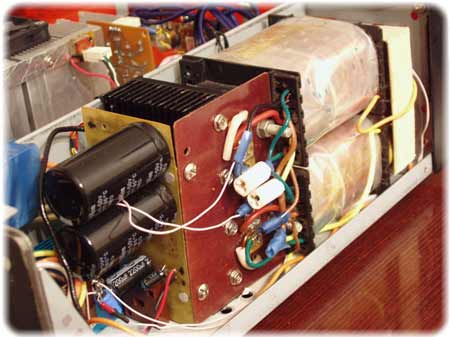
The most boring thing is the corps. As a case, I took an old slim case from a personal computer. I had to shorten it a little in depth, although it was not easy. I think that the case turned out to be successful - the power supply is in a separate compartment and you can put 3 more amplification channels into the case freely.
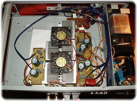
After field tests, it turned out that it is not out of place to put the fans to blow off the radiators, despite the fact that the radiators are very impressive in size. I had to make holes in the bottom and top for good ventilation. The fans are connected through a 100 Ohm 1W trimmer at the lowest speed (see next figure).
Construction cost.
| TDA 7294 | $25,00 |
| capacitors (powerful electrolytes) | $15,00 |
| capacitors (others) | $15,00 |
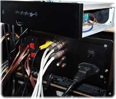
| connectors | $8,00 |
| power button | $1,00 |
| diodes | $0,50 |
| transformer | $10,50 |
| radiators with coolers | $40,00 |
| resistors | $3,00 |
| variable resistors + knobs | $10,00 |
| biscuit | $5,00 |
| frame | $5,00 |
| operational amplifiers | $4,00 |
| Surge Protectors | $2,00 |
| Total | $144,00 |
Yes, it didn’t come cheaply. Most likely, I did not take into account something, I just bought, as always, much more, because I still had to experiment, and I burned 2 microcircuits and blew up one powerful electrolyte (I did not take all this into account). This is the calculation of the amplifier for 5 channels. As you can see, the heatsinks turned out to be very expensive, I used inexpensive but massive CPU coolers, at that time (a year and a half ago) they were very good for cooling processors. Considering that an entry-level receiver can be bought for $ 240, then you can think about whether you need it :), though there is a lower quality amplifier. Amplifiers of this class cost about $ 500.


