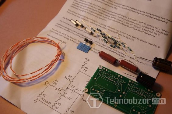
I recently purchased a set of parts with printed circuit board to build a preamplifier to complete the reconstruction of the analogue section of my audio system, which consists of a Rega turntable with an RB300 tonearm and a new Grado Sonata in wood. My return to listening to vinyl was somewhat unexpected for myself; now I am again increasingly buying rock and classic jazz recorded on vinyl. In the old days I had a built-in Harmon Kardon amp with an integrated phono stage.
Preamplifier on LM833
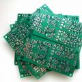
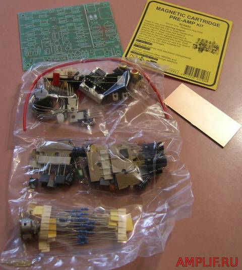
The preamplifier builder consists of printed circuit board and all the components that need to be mounted on it. Everything is laid out and packed in accordance with assembly technology. To this you will need to add a suitable case and power supply. The printed circuit board has several different configuration options, choose based on your needs. There are configurations: RIAA, DECCA, EMI LP, NARTB and Columbia. I chose RIAA and DECCA for myself.
The amplifier circuit includes two integrated circuit LM833 which are low noise two-channel operational amplifiers manufactured using bipolar technology. The microcircuit is specifically designed for use in high-quality audio preamplifier and filter circuits that require a bipolar power supply and a number of parts indicated in the diagram as wiring.
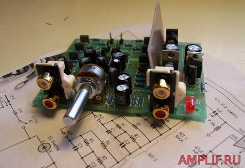
Assembling the board takes no more than one and a half to two hours. I started the assembly by installing small parts, resistors and non-polar capacitors. Then I installed all the electrolytic capacitors. Next were the variable resistor (volume control), connectors, separating shield (separating the power rectifier from the amplifier) and LED.
Microcircuits and voltage stabilizers were soldered last. I also added 0.1 µF capacitors at the output of the power filter to reduce noise. The LED is used as a power supply indicator.
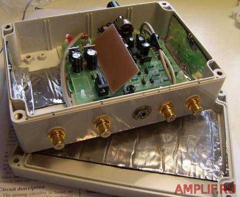
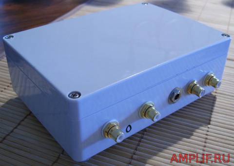
Preamp housing
The case was made of thick plastic. Plastic lends itself well to machining (in this case, drilling) and has sufficient impact strength. Thick aluminum foil was glued to the bottom of the case, sides and lid using epoxy glue as a screen. The printed circuit board is mounted on special mounts used in assembling computers. All audio input and output connectors, as well as the connector for the power supply, are located on the rear wall of the lower part of the case. The front panel has a volume control with a graduated scale.
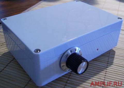
The big advantage of this pre-amplifier configuration is the ability to smoothly control the volume of the reproduced sound. After many hours of listening to songs from vinyl media, I am very pleased with the sound. Including some barely noticeable hiss and hum, which give a unique and natural sound to all classic rock and jazz musical compositions.
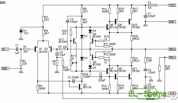
Guitar amplifiers, along with electric guitars themselves, have always been of interest to many beginners and not only musicians. Timbre, gain and overload characteristics are very individual, and the ideal combination varies from one guitar to another. There is no amplifier that completely satisfies all requirements, and this circuit proposal will not be an exception. But it is universal, powerful (about 100 watts) and has all the necessary adjustments. Unlike a store-bought amplifier, if you build a VLF yourself, you can change many things to suit your own needs. The opportunity to experiment is presented in full. And it’s much more honorable to play on your own equipment, because our individuality is manifested primarily through creativity. The proposed guitar amplifier is designed for 100 W of power into a 4 Ohm load. This is the usual power for guitarists, which is enough for both home and concerts.
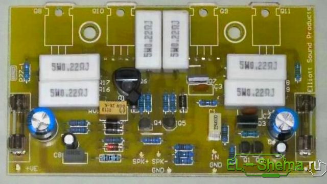
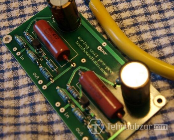
We solder the guitar pre-amp on a separate board, later placed in an interference shield. A photo of the preamp board is shown below. It is based on two operational amplifiers with a tone and gain control unit.
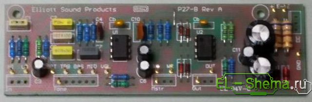
This is a simple but proven circuit design that provides excellent tonality throughout the entire range. The design is ideal for those guitarists who would like to get great sound. The tone controls have enough range to cover almost anything, from violin to bass guitar.
The preamplifier uses dual op-amp for amplification. The transistor is connected according to the emitter follower circuit and has a low output impedance, after the master volume control. As shown in the diagram, there is a typical guitar input from which you can get a very fat overdrive and then adjust it to a suitable level. Please note that when using the TL072 operational amplifier, noise may occur with big amount high frequencies. We highly recommend using the OPA2134 op amp from Texas Instruments, then you will truly have the quietest guitar amp you've ever heard!
The module's power is connected directly to the main +/-35 V bus of the power amplifier. You need to use 1 W zener diodes (D5 and D6), and 680 Ohm resistors R18 and R19 should also be 1 W each.
For greater gain, we recommend reducing R11 to at least 2.2 kOhm. If the bright switch makes the sound too bright (too much high frequency), you need to increase the resistor R5. The output diodes are designed to allow the preamp to create "soft" clipping as the volume increases.
Make sure the input connectors are isolated from the chassis. This helps prevent noise, especially when the guitar amp is connected to a different power source.
Amplifier
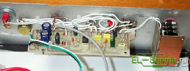
The photo below shows a fully assembled UMZCH printed circuit board. The TIP35 and TIP36 output stage transistors ensure reliability in the harshest stage conditions. Other features of the circuit include protection against short circuit- bias components of diodes D2 and D3.
Short circuit protection limits the output current to a relatively safe level. The protection will limit the peak output current to approximately 8 amps. The bias current is adjustable and should be set at about 25 mA at rest. Transistors TIP3055/2966 or MJE3055/2955 can also be used for UMZCH. The circuit allows you to connect up to two 8-Ohm acoustic speakers(4 ohms each). Do not use speakers less than 4 ohms into this amplifier - it is not designed for such low impedance!
ULF power supply
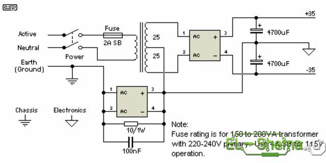
The power transformer should be toroidal for best performance and minimum interference. The amplifier is designed for a maximum supply of +/-35V and this value should not be exceeded. The transformer should be rated for 25-0-25 volts, and no more. Less is fine if you don't need the full 100 watts. The transformer power should be 150VA (3 A secondary current). More than 250VA is overkill. Use good quality PSU filter electrolytes, since they will be subject to current and temperature loads. The current of the diode bridge rectifier should be 35 A. Mounting type - on a chassis with thermal paste.
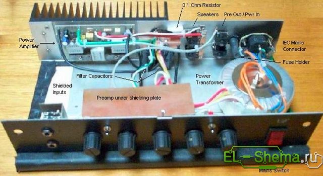
All fuses must be as specified in the diagram - do not be tempted to use larger ones. The input and output connections are shown in the figure.
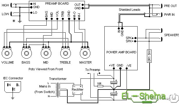
Nests Preamp out And power amp in allow you to insert effects into the audio path, such as compression, reverb, digital effects and others. The preamplifier output is connected so that the preamplifier signal can be removed without turning off the power amplifier, so it can be used for direct audio supply. This is especially useful for bass. The preamp output can also be used for .
Setting up a guitar amp
- Before the power is turned on for the first time, temporarily install 22 ohm 5 W resistors instead of fuses. Do not immediately connect the load (AC)! When applying power, check that the DC output voltage is less than 1 V. Check all transistors for heat - if any element is hot, turn off the power immediately, then look for the error.
- If everything is good, connect sound system and the signal source and make sure that the sound is not distorted (for example, connect music from the player).
- If the VLF passes all these tests, remove the 22 ohm resistors and reinstall the fuses. Disconnect the load speaker cable and turn the unit back on. Make sure that the DC voltage at the AC terminals does not exceed 100 mV, and again check the heating on all transistors and resistors.
- Once you are sure everything is good, set the bias current. Connect a multimeter between the collectors of Q10 and Q11 - you are measuring the voltage drop across two 0.22 ohm resistors R20 and R21. The required quiescent current is 25 mA, so the voltage across the resistors should be set to 11 mV. The value setting is not too critical, but lower currents will result in less dissipation in the output transistors.
- After this, it remains to adjust the offset when the temperature of the body and all parts of the guitar amplifier stabilizes. Often temperature and current are slightly interdependent. That's it - the design is ready!
Part 1 . Blocks of VHF devices. Article 2. LF amplifier blocks.
AF power amplifiers.
Amateur designs of various options for low-frequency power amplifiers can be found in any amateur radio reference book and magazines, such as “Radio”, “Radiomir. KB and VHF", "Radio Amateur", "Radio Constructor" and many others. So the radio amateur has a huge selection of ULF, for every taste. , In this article I will provide descriptions of those designs that I myself have tested and used in practice.
When choosing an amplifier circuit, you should remember that amateur radio stations do not need high-quality ULF with a huge audio frequency bandwidth. For a communication receiver, the required bandwidth of LF signals lies in the range of 300 ... 3000 Hz. This band is quite sufficient for high-quality reception of signals by human hearing organs and for the operation of devices digital communications.
All frequencies above or below the specified range will only cause harm. Therefore, a low-pass filter must be installed at the amplifier input. In addition, the amplification of high frequencies can be suppressed by selecting correction capacitors and resistors. You can significantly increase the sensitivity of the ULF by increasing the resistance R2 to 120 Ohms.
ULF on m/skh K174UN7
K174 series microcircuits provide the radio amateur with a large selection of different radio designs. K174UN7 is a low-frequency amplifier with the following parameters:
Supply voltage 15 V;
Rated output power 4.5 W;
Harmonic coefficient for output power 0.05 W - 2%, for 4.5 W - 10%;
Frequency band from 40 to 20000 Hz;
Input impedance 50 kOhm;
Load resistance 4 Ohms;
Gain 40 dB;
The maximum amplitude value of the current in the load is 1.75 A;
The maximum amplitude value of the output voltage is 2 V;
The permissible DC voltage at pin 7 is 15 V;
Allowable constant voltage at pin 8 is from minus 0.3 to 2 V;
It is unacceptable to apply external DC voltage to pins 5, 6, 12.
The microcircuit must be placed on a heat sink - a cooler.
In Fig. 2.1 is given circuit diagram ULF, made on the K174UN7 microcircuit.
This amplifier has a wide audio frequency bandwidth. Therefore, a low-pass filter must be installed at the output of the amplifier. In addition, it is possible to suppress the amplification of high frequencies by selecting correction capacitors and resistors. You can significantly increase the sensitivity of the ULF by increasing the resistance R2 to 120 Ohms.
The amplifier requires virtually no adjustment. Subsequently, after the complete production of the entire radio receiver with this ULF, you can try to change the output frequency response selection of values for correction capacitors and resistors (if necessary!).
In the K174 series there are other low-frequency amplifier microcircuits suitable for communications technology.
ULF on transistors - option 1.
For those who like to work with transistors of old brands, I present a tested circuit of a simple ULF on transistors, shown in Fig. 2.2.
The amplifier's input sensitivity is approximately 0.25V, so for its normal operation As part of the radio receiver, it is necessary to install another low-frequency amplifier, the so-called “preliminary ULF”, between the detector and this amplifier, which should amplify the signals received from the detector to a value of 0.25V.
The output power of the amplifier is approximately 2 W, the harmonic distortion is no more than 3%, the output must have a loudspeaker with a coil resistance of 5 ... 8 Ohms.
Stabilization of the output stage mode is carried out using diode VD1. The diode should be selected according to the criterion of obtaining the least possible distortion with a small input signal. You can try diodes D18, D310 and others, but remember the indispensable requirement: replacing the diode can only be done with the power turned off.
The amplifier can also operate at a lower supply voltage. With a supply voltage of 9V and a speaker resistance of 8 Ohms, the output power will be approximately 1 W, and with a supply voltage of 6V - approximately 0.5 W
The setting is carried out by selecting resistors R1 and R9 so that the voltage on the positive electrode of capacitor C4 is equal to half the supply voltage. In this case, the current value in silent mode through transistors VT4 and VT5 should be within 2...3 mA.
Using a similar scheme, you can make a ULF using modern transistors.
ULF on transistors - option 2.
In Fig. Figure 2.3 shows a schematic diagram of another version of the transistor ULF. This circuit is similar to the ULF circuit in the design of the basic receiver of a KB radio station developed by Ya. S. Lapov. In this circuit, compared to the analogue, different transistors are used.
Setting up the ULF consists of selecting resistance R1 to such a value that at the positive electrode of capacitor C4 (at the common point for transistors VT3 and VT4) the voltage is half the supply voltage. Just like the previous ULF, this amplifier needs an additional (pre-amplifier).
LF pre-amplifiers. Pre-amplifier on transistors.
In household radios, low-frequency preamplifiers are usually supplemented with audio frequency correction functions. In radio receivers for communication there is no need for such correction, because the range of reproduced ULF frequencies of the communication receiver should not go beyond the range of 300 ... 3000 Hz. Therefore, preamplifier circuits can be very simple. In Fig. Figure 2.4 shows a diagram of a simple, but quite effective transistor low-frequency pre-amplifier. The circuit is presented in two versions, which differ only in the structure of the transistors used.
Setting up the ULF consists of selecting resistance R2 to a value at which in silent mode the voltage drop across resistor R4 is exactly half the value of the supply voltage. In other words, the voltage at the collector of transistor VT2 should be equal to half the supply voltage.
Preliminary ULF on microcircuits.
As a rule, the developer of a new radio receiver strives to distribute the total gain between its stages so that the largest share of the gain falls on the IF and ULF amplifiers. Therefore, the desire of the radio designer to create ULF with the highest possible gain is understandable. A similar problem can be solved using low-frequency preamplifiers based on operational amplifiers. In Fig. 2.5 shows one of possible schemes low-frequency preamplifier on an operational amplifier type K140UD6. You can also use K140UD7, K140UD12 and others.
The gain shown in Fig. 2.5 amplifier is equal to the ratio of the sum of values (R5 + R6) to the resistance value of resistor R1. For example, if the total value of resistances R5 and R6 is 50 ohms, and the resistance value of resistor R1 is 10 ohms, then the gain will be 10.
Setting up the amplifier consists of selecting the most convenient resistance value of the variable resistor R5. Strictly speaking, a variable resistor is not needed here. Selection can be made using various fixed resistors.
In Fig. Figure 2.6 shows a pre-amplifier circuit based on the K548UN1 microcircuit. This microcircuit consists of two identical low-noise ULFs.
The parameters of the amplifier depend on the depth of feedback, which is determined by the ratio of the resistances of resistors R1 and R3. With the resistance values indicated in the diagram, the amplifier is characterized by the following parameters:
Voltage gain 100 (equal to the ratio of resistances R1/R3),
The input impedance is 300 kOhm,
Output - no more than 1 Ohm,
Highest operating frequency of at least 100 kHz.,
Harmonic coefficient at a frequency of 1 kHz with a load resistance of 10 kOhm no more than 0.05%,
Noise figure (measured in a frequency band up to 23 kHz with a signal source resistance of 10 kOhm) no more than 2.
If the voltage gain is increased to 1000, the highest operating frequency is reduced to approximately 20 kHz. and the harmonic distortion increases to 0.1%. Correction capacitor C is included if it is necessary to limit the range of operating frequencies. The pins of the microcircuit shown in brackets refer to the second amplifier located in the same housing.
Combined ULF option
In Fig. 2.7 shows the principle electrical diagram low-frequency amplifier, which includes a pre-amplifier based on the K140UD6 operational amplifier and a power amplifier with 5 transistors. Feature transistor amplifier power is that this amplifier is designed to operate in class AB mode, which is characterized by low linear distortion.
With the values of radio components indicated in the diagram. ULF provides output power about 1 W and has efficiency. about 60%. Input resistance is about 300 Ohms, output - 10...20 Ohms. The transistor power amplifier is configured by selecting resistance R8 to a value at which the voltage at the junction point of the collectors of transistors VT4 and VT5 becomes equal (in silent mode) to exactly half the supply voltage.
The operational amplifier stage has no special features.
Low Pass Filters
As has already been said when considering the block diagram of the receiver, after detection it is necessary to clean the received signal from the side frequencies present in it, i.e. signal filtering is required. After detection, the signal will certainly contain both high (above 3000 Hz) and low (below 300 Hz) side detection results and various interferences, for example, with a frequency of 50 Hz from the power source. By the way, with poor filtering, frequencies of both 100 Hz and 200 Hz can be induced from the power source - these are higher harmonics from the frequency electrical network 50 Hz.
The signal has to be filtered several times during its conversion in the receiver, but here we are considering the circuits of low-frequency cascades and it is the designs of bandpass low-pass filters that are subject to consideration.
The main filtering of the signal after detection should be carried out by low-pass filters (LPF). International standard sets the upper limit frequency of the telephone channel to 3400 Hz, which ensures good speech intelligibility. By improving the noise immunity and selectivity of receivers, amateurs are content with a narrower band from the top cutoff frequency 2700...3000 Hz.
The simplest low-pass filter, installed at the output of a detector or the last (telegraph) mixer of a receiver or transceiver, is advisable to use LC elements according to the so-called U-shaped circuit (Fig. 2.8.
In my opinion, this is the most effective of these filters and can be successfully used even in receivers direct conversion. Its losses are negligible, the selectivity is 23 dB at double the frequency of the cutoff signal, and 32 dB at triple the frequency of this signal. For large detunings it is equal to 60 dB per decade (a tenfold increase in frequency). The relationships between the filter elements are determined by the formulas: C1 = C2 = 1/(2*π*fc*R), L1 = R/(π*fc), where fc is the cutoff frequency, n-number pi=3.14. Resistance R1 is usually the input impedance of the ULF. It is enough to maintain the values of L and C with an accuracy of 10%, so the filter does not require adjustment.
V.T. Polyakov, author of the book “FM Broadcast Receivers with Phase-Locked Loop,” recommends creating a slight boost in the upper frequencies of the audio spectrum. He believes that such a rise is useful for improving intelligibility, so it is advisable to design the filter with a resistance of 1.5...2 times less than the actual load. Typical element values for fc = 3 kHz are as follows: C1 = C2 = 0.05 μF, L1 = 0.1 H, R = 1 ... 2 kOhm.
The coil is wound on a K16x8x4 ring magnetic core made of 2000NM ferrite and contains 260 turns of any suitable insulated wire. Toroidal coils are good because they are little susceptible to extraneous magnetic interference and most often do not require shielding.
The INDUKTIW program will help you calculate any elements of the oscillatory circuit, which you can get on the Internet at the website at: http://r3xb-tga.narod.ru/ or http://r3xb.by.ru.
One of the windings of a miniature transformer from portable successors can also serve as the filter inductance; the primary winding of the output transformer is best suited.
There is usually no need to filter frequencies below 300...400 Hz - this role is played by isolation capacitors in the ULF, the capacitance of which is selected from the condition C = 1/(2*п*fн*R), where fн is the lower frequency of the audio spectrum, R is input impedance of the stage following the coupling capacitor.
If you have this moment there is no suitable inductor, you can make an RC filter by replacing the coil with a 300 ... 800 Ohm resistor. The filtering will be somewhat worse, but the receiver will remain operable. In some cases, the value of this resistor can be increased to 3 kOhm.
Instead of a conclusion.
In amateur radio practice, a huge number of different schemes are used. Each of us uses those schemes that are more convenient for him due to the available set of parts, or for some other reasons that are understandable only to him. In this series of articles I will present the schemes that I use in my practice. Some will like them, some won't. I don't think at all that the schemes I have chosen are the best. Surely there are more convenient circuits on modern radio components. Look for what you like.
Using JFET transistors in a preamplifier, you can obtain a noticeable increase in signal level without loss of quality, naturally, if you assemble them as a separate unit on a small printed circuit board. This preamplifier kit will be especially useful for matching powerful tube amplifiers with a weak audio source, for example, the linear output of a smartphone or player, or a phono preamplifier.
There is even a separate industrial kit for assembling a preamplifier, which includes a printed circuit board, the transistors themselves, and several passive components for the printed circuit board. All that remains is to find your own case, a 12-24 V power supply, and various connectors. Here are the characteristics of the set:
- Circuit using jfet transistors 2SK170;
- Approximately ~30dB gain;
- Capacitor K40U paper-in-oil;
- The circuit requires an external 12-24V DC power supply (batteries work well too);
- Assembled dimensions 10x5x3 cm.
This kit is easy to solder and can be assembled in less than an hour. If you look at the diagram, you will see a very simple solution. There are no settings as such - everything works right away.
As for pass-through capacitors, this type is even used in many tube projects. They are inexpensive and have good sound.
Most truly low noise preamps run on battery power. We like batteries for several reasons; They are very portable, no mains power required, power consumption is very low with most devices, especially using only 2 jfet transistors.
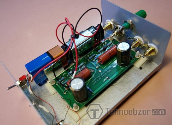
Amplifier design
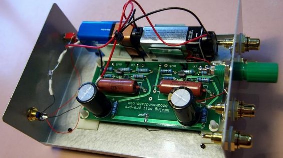
Typically, gold-plated RCA connectors are used for inputs and outputs. Through two 9 V batteries, a supply voltage of 18 V is supplied to the amplifier stage. Currently, Panasonic batteries are used, but it makes no difference. To monitor the condition of the batteries, a test point is located on the front panel of the units. Thus, testing batteries does not require opening the case. The clamps hold the 9V battery inside and a dim yellow LED indicates the On status.