n1.doc
3.3. Power losses in transformers
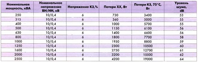
In the reference literature, the values of the characteristics of the transformer at nominal load are given:? Р хх - active no-load losses, kW; ? R kz - losses short circuit, kW; I n - rated current, A; I xx - no-load current, A;S n - rated power of the transformer, kVA; U kz% - short-circuit voltage,%.
Accordingly, we obtain for the rated load of the transformer:
jet losses idle move
Reactive short circuit losses
 .
.
At a load different from the nominal (  ):
):
active short-circuit losses are  ;
;
reactive short-circuit losses  .
.
Total power losses in the transformer taking into account the load:
active
 ;
;
jet
 .
.
3.4. Operating modes and selection of the number and power of transformers
With an increase in the power of transformers, short-circuit currents increase. Therefore, the unit power of transformers supplying electrical installations up to 1000 V is limited by the permissible values of the short-circuit current. It is considered impractical to use transformers with secondary voltage up to 0.4 kV with a capacity of more than 2500 kVA. The number of standard sizes of transformers in the shop should be minimal.Single-transformer substations are recommended to be used if there are power receivers in the shop (building) that allow a power outage for the time of delivery of the "warehouse" reserve, or when redundancy is carried out on low voltage lines from neighboring transformer substations, that is, they are acceptable for consumers of III and II categories , as well as in the presence of a small number (up to 20%) of category I consumers in the 380 - 660 V network.
It is recommended to use two-transformer substations in the following cases: with the predominance of consumers of category I and the presence of consumers of a special group; for a concentrated shop load and stand-alone facilities for general plant purposes (compressor and pumping stations); for workshops with high specific load density (above 0.5 - 0.7 kVA / m 2).
When choosing the number and capacity of workshop transformers, the consumed load of the workshop and the specific load density n are taken into account. With a load density of up to n = 0.15 kVA / m 2, it is advisable to use transformers with a capacity of up to 1000 and 1600 kVA, with a density of 0.15 - 0.35 kVA / m 2 - with a power of 1600 kVA. With a density of more
0.35 kVA / m 2 the expediency of using transformers with a capacity of 1600 or 2500 kVA is justified by technical and economic calculations according to.
The approximate choice of the number and capacity of shop transformers is made according to the specific density n load
n = S p / F,
where S p is the estimated load of the shop (building, department), kVA; F - area of the shop (building, department), m 2.
It is recommended to select the rated power of transformers according to the rated power of the normal and emergency modes work proceeding from the rational load in normal mode and taking into account the minimum required redundancy in the post-emergency mode. The rated power of transformers S n.t is determined by the average load P s for the maximum loaded shift:
S n.t = P s / (N k s),
where N is the number of transformers; k s - load factor of the transformer.
Optimal loading of workshop transformers depends on the reliability category of electricity consumers, on the number of transformers and the method of redundancy. It is recommended to take the following load factors of transformers: for shops with a prevailing load of category I for two-transformer transformer substations k z = 0.75 - 0.8; for workshops with a predominant load of category II for single-transformer substations in the case of mutual redundancy of transformers at low voltage k z = 0.8 - 0.9; for workshops with a load of category III k z = 0.95 - 1.
When choosing the number and capacity of shop transformers, the issue of the economically feasible value of reactive power transmitted through transformers to the network with a voltage of up to 1 kV should be simultaneously resolved.
The optimal number of transformers and their capacity are found at the minimum of the reduced costs (thousand rubles):
 ,
,
where N is the number of transformers and switching devices;
E n - coefficient of efficiency of capital investments (E n = 0.12);
E ai - depreciation rate;
K i - the cost of the i-th transformer or switching device, thousand rubles;
With about - the cost of one kW. h of electricity;
W a - annual electricity losses (kWh) in one transformer;
n is the number of transformers.
where?  and?
and?  reduced power losses of no-load and short-circuit in the transformer, kW;
T about - the number of hours of connecting the transformer to the network during the year;
Tr is the annual number of hours of operation of the transformer under load;
 is the load factor of the transformer.
Reduced active no-load losses
 ,
,
where  .
.
Reduced active short-circuit losses
 , kW,
, kW,
where  .
.
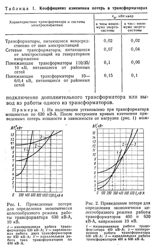
КП - coefficient of increase of active power losses in connection with the transfer of reactive power (see table).
Table *
| Characteristics of the transformer and power supply system | kp, kW / kvar |
|
| Transformers powered directly from substation busbars | ||
| Mains transformers powered by generator voltage power plants | ||
| Step-down transformers 110/35/10 kV, powered by district networks | ||
| Step-down transformers 6 - 10 / 0.4 kV, powered by district networks | ||
The obtained values of the reduced active losses of active power? and? substituted in the expression for? W a and then determine the reduced costs Z.
In simplified calculations, it is allowed to choose transformers according to the reduced active power losses in them:
 .
.
Choose the option with the smallest  .
.
Do they depend on the load factor? and the number of transformers (see fig. *).
Figure 3.1. Dependence of the reduced active power losses in transformers on their load and number
What is the critical load factor? critical , at which it is necessary to switch to the operation of two transformers is determined from the expression:
 ,
,
where  .
.
3.5. Voltage losses in transformers and voltage regulation
In transformers, under the action of the load, a voltage loss occurs (see table 3.1).
Table 3.1
Voltage loss (%) in transformers at rated load (? = 1)
| Rated power transformer, kVA | Power factor (cos?) |
|||||
| 0,7 | 0,8 | 0,85 | 0,9 | 0,95 | 1,0 |
|
| 100 | 4,27 | 4,01 | 3,81 | 3,54 | 3,02 | 1,97 |
| 160 | 4,16 | 3,85 | 3,62 | 3,32 | 2,77 | 1,66 |
| 250 | 4,07 | 3,73 | 3,50 | 3,18 | 2,61 | 1,48 |
| 400 | 4,02 | 3,67 | 3,42 | 3,10 | 2,52 | 1,38 |
| 630 | 4,67 | 4,18 | 3,85 | 3,42 | 2,66 | 1,20 |
| 1000 | 4,68 | 4,19 | 3,86 | 3,44 | 2,67 | 1,22 |
| 1600 | 4,62 | 4,12 | 3,78 | 3,35 | 2,58 | 1,12 |
When the load of the transformer differs from the rated one, the voltage loss is determined by the formula:
U t% =? (U а% cos? +? U р% sin? )
where U a% is the active component of the voltage loss in the transformer U a% = 100P kz / S n.t,%;
U р% is the reactive component of the voltage loss in the transformer
 ,
,
where U kz% - short-circuit voltage,%; P kz - short-circuit power losses, kW; S n.t - rated power of the transformer, kVA; ? - the load factor of the transformer,? = I p / I n.t.
Example 8.2 For the TMZ-1000/10 / 0.4 transformer, determine the voltage loss under the action of the load Pp = 575 kW at cos = 0.9. The solution is given in table. 3.2.
Table 3.2
Determination of the available voltage loss in the network
low voltage
| Calculated values and formulas | KTP number |
||
| KTP 2nd section | |||
| Rated load current  , A , A | 1097 | ||
| Rated current of the transformer  , A , A | 1443,4 | ||
| Transformer load factor? = I p / I n.t. | 0,76 | ||
| Options | P kz, kW | 10,8 | |
| transform- | S n.t, kVA | 1000 | |
| Torah | U cs%,% | 5,5 | |
| A loss stresses in the transformer | U a% = 100P kz / S n.t,%;
? U т% =? (U а% cos? +? U р% sin?) | 1,08 5,39 | |
 , %
, %In conditions normal work electrical receivers, voltage deviations at their terminals from the nominal value are allowed within the following limits:
5%… + 10% - at the terminals of electric motors and apparatus;
2.5%… + 5% - at the clamps of working lighting devices.
Accordingly, the permissible (available) value of the voltage loss in electrical network low voltage is:
for power networks
U with% = U 0% -? U t% - U min.dv%;
U c% = 105 -? U t% - 95% = 10% -? U t%.
for lighting networks
U with% = U 0% -? U t% - U min lamp%;
U c% = 105 -? U t% - 97.5% = 7.5% -? U t%,
where U 0% is the no-load voltage or the rated voltage of the secondary winding of the transformer in percent; ? U t% - voltage loss in the transformer; U min.dv% and U min.lamp% are the minimum allowable voltages, respectively, on motors and on lamps.
Due to the fact that the voltage at the terminals of power transformers depends on the load, to maintain the required voltage in the network, all power transformers with a capacity of more than 6300 kVA are equipped with voltage regulators. For all transformers of lower power, the rated voltage of the secondary windings is set 5% higher than the rated one.
Annotation.
The article is devoted toanalysis of the calculation of losses in a two-winding power transformer
... The authors also suggestpractical implementation of the method for calculating transformer losses inMSExcel.
Keywords:
power two-winding transformer, calculation of electricity losses, method of average loads.
The transfer of electrical energy from the source to the final consumer is inevitably associated with the loss of part of the power and energy in the power supply system. With an increase in electricity tariffs, the economic significance of the problem of electricity losses increases, due to the inclusion of standard values of losses in the tariff, as well as a decrease in the profit of grid companies due to excess losses. It also makes it difficult to connect additional capacities to electric grids, and reducing electricity losses in electric grids is an effective means of increasing their throughput, which allows grid companies to expand the scope of services for consumers' access to grids. The regulatory framework for calculating electricity losses is the Instruction on the organization in the Ministry of Energy Russian Federation work on the calculation and substantiation of standards for technological losses of electricity during its transmission through power grids, approved by order of the Ministry of Energy of the Russian Federation dated 30.12.2008 No. 326 (registration of the Ministry of Justice of Russia reg. No. 13314 dated 12.02.2009).
Electricity losses in transformers are one of the types of technical electricity losses due to the peculiarities of the physical processes occurring during the transmission of energy. Consider the methodology for calculating electricity losses in a two-winding power transformer for a billing period (month, quarter, year).
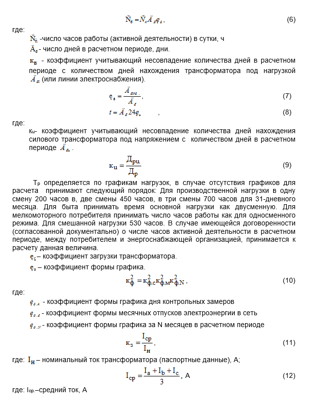
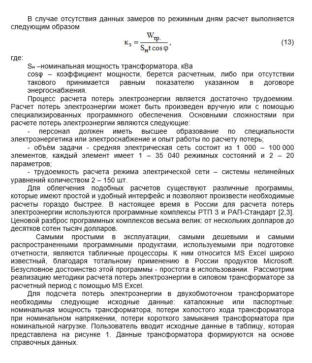
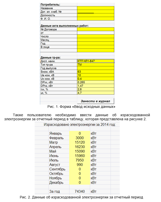
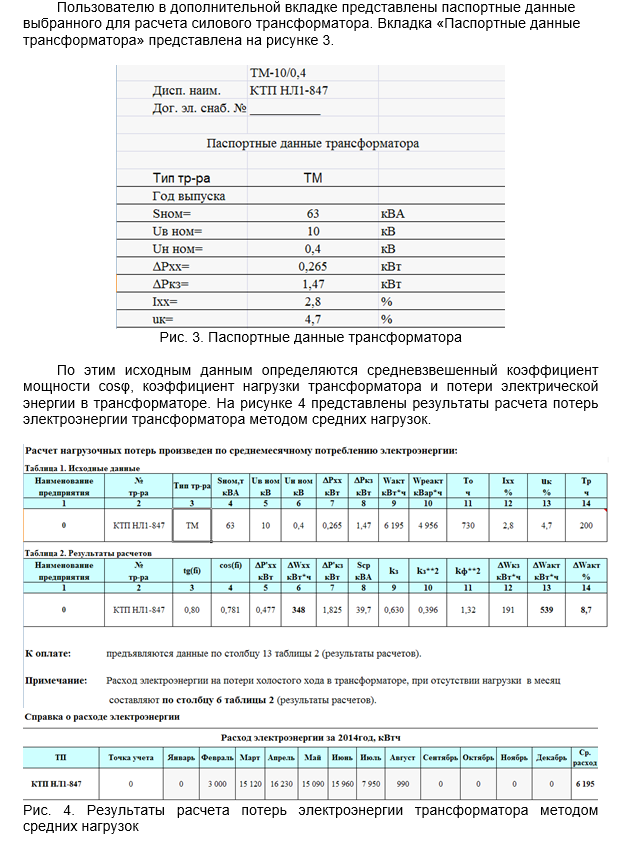
In Russia and abroad, several dozen software packages have been developed to solve various problems associated with calculating electricity losses. These complexes differ as a set of functional and service capabilities, cost, reliability and other parameters. But the use of MS Excel continues to be widely used by Russian power grid companies for calculating electricity losses, since it does not require special training of personnel and has a clear and intuitive interface.
- Yu.S. Zhelezko, A.V. Artemiev Calculation, analysis and regulation of electricity losses in electrical networks: a guide for practical calculations. -M .: Publishing house NTs ENAS, 2003.
- Guidelines for determining the losses of electrical energy in urban electrical networks with a voltage of 10 (6) -0.4 kV. (Developed by the Russian Joint Stock Company Roskommunenergo and ZAO Automated Control System Mosoblelektro. Approved by the State Energy Inspectorate of the Ministry of Energy of Russia (09.11.00 # 32-01-07 / 45)).
- Vorotnitsky V.E., Kalinkina M.A. Calculation of rationing and reduction of electrical energy losses in electrical networks. Study guide. 2nd ed.-M .: IPKgosluzhby, 2001.
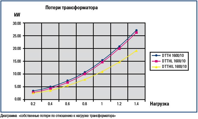
The main characteristics of a transformer are primarily the winding voltage and the power transmitted by the transformer. The transfer of power from one winding to another is carried out electromagnetically, while part of the power supplied to the transformer from the mains supply is lost in the transformer. The lost part of the power is called losses.
When power is transmitted through a transformer, the voltage on the secondary windings changes with a change in load due to a voltage drop in the transformer, which is determined by the short-circuit resistance. The power loss in the transformer and the short-circuit voltage are also important characteristics... They determine the efficiency of the transformer and the operating mode of the electrical network.
Power loss in a transformer is one of the main characteristics of the economy of a transformer design. The total normalized losses consist of no-load losses (XX) and short-circuit losses (SC). At idle (no load is connected), when the current flows only through the winding connected to the power source, and there is no current in the other windings, the power consumed from the network is spent on creating an idle magnetic flux, i.e. for magnetization of a magnetic circuit consisting of sheets of transformer steel. Since, the direction of the magnetic flux also changes. This means that the steel is magnetized and demagnetized alternately. When the current changes from maximum to zero, the steel is demagnetized, the magnetic induction decreases, but with some delay, i.e. demagnetization is delayed (when the current reaches zero, the induction is not zero point N). The delay in the magnetization reversal is a consequence of the resistance of the steel to the reorientation of elementary magnets.
The magnetization curve with a change in the direction of the current forms a so-called, which is different for each grade of steel and depends on the maximum magnetic induction Bmax. The area covered by the loop corresponds to the power spent on magnetization. Since the steel heats up during magnetization reversal, the electrical energy supplied to the transformer is converted into heat and dissipated into the surrounding space, i.e. is irretrievably lost. This is physically the loss of power for magnetization reversal.
In addition to losses due to hysteresis, when the magnetic flux flows through the magnetic circuit, arise. As you know, the magnetic flux induces an electromotive force (EMF), which creates a current not only in the winding located on the core of the magnetic circuit, but also in its metal itself. Eddy currents flow in a closed loop (vortex motion) in the place of steel in a direction perpendicular to the direction of the magnetic flux. To reduce eddy currents, the magnetic circuit is assembled from separate insulated steel sheets. In this case, the thinner the sheet, the less the elementary EMF, the less the eddy current created by it, i.e. less power loss from eddy currents. These losses also heat up the magnetic circuit. To reduce eddy currents, losses and heating, steels are increased by introducing additives into the metal.
In any transformer, the consumption of materials must be optimal. At a given induction in the magnetic circuit, its size determines the power of the transformer. Therefore, they try to have as much steel as possible in the section of the core of the magnetic circuit, i.e. with the selected outer size, the fill factor kz should be the largest. This is achieved by applying the thinnest layer of insulation between the steel sheets. Currently, steel is used with a thin heat-resistant coating applied in the process of making steel and making it possible to obtain kz = 0.950.96.
In the manufacture of a transformer, due to various technological operations with steel, its quality in the finished structure deteriorates somewhat and losses in the structure are obtained by about 2550% more than in the original steel before its processing (when using coiled steel and pressing the magnetic circuit without studs).
A transformer is a device that is designed to convert the electrical power of the network. This installation has two or more windings. In the course of their operation, transformers can convert the frequency and voltage of the current, as well as the number of phases in the network.
In the course of performing the specified functions, power losses are observed in the transformer. They affect the initial amount of electricity that the device produces at the output. What are losses and efficiency of a transformer will be discussed below.
Device
The transformer is a static device. It is powered by electricity. In this case, there are no moving parts in the design. Therefore, an increase in electricity costs due to mechanical reasons is excluded.
With the operation of power equipment, electricity costs increase during non-working hours. This is due to an increase in active no-load losses in steel. At the same time, a decrease in the nominal load is observed with an increase in the reactive-type energy. The energy losses that are determined in the transformer are related to the active power. They appear in the magnetic drive, on the windings and other components of the unit.
Loss concept
When the unit is in operation, part of the power goes to the primary circuit. It dissipates in the system. Therefore, the power supplied to the load is determined at a lower level. The difference is the total power reduction in the transformer.
There are two types of reasons for which there is an increase in the energy consumption of equipment. They are influenced by various factors. They are divided into the following types:
- Magnetic.
- Electrical.
They should be understood in order to be able to reduce electrical losses in a power transformer.
Magnetic loss
In the first case, the losses in the steel of the magnetic drive consist of eddy currents and hysteresis. They are directly proportional to the mass of the core and its magnetic induction. The iron itself, from which the magnetic drive is made, affects this characteristic. Therefore, the core is made of electrical steel. The plates are made thin. There is an insulation layer between them.
Also, the frequency of the current affects the decrease in the power of the transformer device. Magnetic losses also grow with its increase. This indicator is not affected by the change in device load.
Electrical losses
A decrease in power can be determined in the windings when they are heated by current. In networks, such costs account for 4-7% of the total amount of energy consumed. They depend on several factors. These include:
Power losses in transformers are variable. It is affected by the square of the current in the circuits.
Calculation method
Transformer losses can be calculated using a specific method. This will require obtaining a number of initial characteristics of the transformer operation. The technique presented below is applied to double-winding varieties. For measurements, you need to obtain the following data:
- System power rating (Nm).
- Losses determined at no-load (XX) and rated load.
- Short circuit losses (SCL).
- The amount of energy consumed per a certain amount of time (PE).
- The total number of hours worked per month (quarter) (HR).
- The number of hours worked at the nominal load level (LF).
Having received this data, the power factor (angle cos φ) is measured. If the system does not have a reactive power meter, its tg φ compensation is taken into account. For this, the dielectric loss tangent is measured. This value is converted into a power factor.
Calculation formula
The load factor in the presented method will be determined by the following formula:
K = Ea / NM * OCH * cos φ, where Ea is the amount of active electricity.
What losses occur in the transformer during the loading period can be calculated according to the established method. For this, the formula is applied:
P = XX * OCH * PKZ * K² * LF.
Calculation for three-winding transformers
The above technique is used to evaluate the performance of two-winding transformers. For equipment with three circuits, it is necessary to take into account a number of data. They are indicated by the manufacturer in the passport.
The calculation includes the rated power of each circuit as well as their short-circuit losses. In this case, the calculation will be made according to the following formula:
E = ESN + ENN, where E is the actual amount of electricity that passed through all the circuits; ESN - electricity of the medium voltage circuit; ENN - low voltage electricity.
![]()
Calculation example
To make it easier to understand the presented methodology, you should consider the calculation using a specific example. For example, you need to determine the increase in energy consumption in a 630 kVA power transformer. It is easier to present the initial data in the form of a table.
| Designation | Decoding | Meaning |
|---|---|---|
| NN | Rated voltage, kV | 6 |
| Ea | Active electricity consumed per month, kWh | 37106 |
| NM | Rated power, kVA | 630 |
| PKZ | Loss of short circuit of the transformer, kW | 7,6 |
| XX | No-load losses, kW | 1,31 |
| OCH | The number of hours worked under load, h | 720 |
| cos φ | Power factor | 0,9 |
Based on the data obtained, a calculation can be made. The measurement result will be as follows:
P = 0.38 kW * h
% loss is 0.001. Their total number is equal to 0.492%.
Measuring efficiency
When calculating losses, the efficiency is also determined. It shows the ratio of active type power at input and output. This indicator is calculated for a closed system according to the following formula:
Efficiency = M1 / M2, where M1 and M2 are the active power of the transformer, determined by measurement on the input and output circuits.
The output value is calculated by multiplying the rated power of the installation by the power factor (cosine of the angle j squared). It is taken into account in the above formula.
In transformers 630 kVA, 1000 kVA and other powerful devices, the indicator can be 0.98 or even 0.99. It shows how efficiently the unit works. The higher the efficiency, the more economically energy is consumed. In this case, the cost of electricity during the operation of the equipment will be minimal.
Having considered the methodology for calculating the power losses of a transformer, short circuit and no-load, it is possible to determine the efficiency of the equipment, as well as its efficiency. The calculation method involves using a special calculator or making a calculation in a special computer program.
Electricity losses in transformers are the most important indicator of the efficiency of their operation, an indicator of the state of the electricity metering system. It shows the problems that require solutions in the development, reconstruction and technical re-equipment are electrically connected, which causes the transmission of power not only electromagnetic, but also electrically.
Autotransformers are widely used in networks with a voltage of 150 kV and higher due to their lower cost and lower total losses of active power in the windings compared to transformers of the same power. The initial data for calculating electrical energy losses in power transformers are: type of transformers; power; rated current, no-load and short-circuit losses (according to passport data); information about the disconnection of transformers during the billing period; the average maximum operating current of the transformer, taken from the daily load curves during the period of control measurements:
The amount of active energy received in the power transformers, Wtr, the amount of active energy received in the subscriber transformers Wtr.a (kW ∙ h) for the billing period.
Annual electricity losses in a power transformer are determined: where t is the number of operating hours of the transformer for the billing period; τ is the time of maximum losses (the conditional time during which the losses in the active resistance of a network element at a constant maximum load would be equal to energy losses in the same element for converting electricity from one voltage to another, communication between individual elements of the electrical network, voltage regulation and power flows They are a static electromagnetic device with two or more inductively coupled windings. By purpose, transformers are divided into step-up and step-down, according to the number of windings - into 2, 3 and split windings. An autotransformer differs from a power transformer in that his two windings
estimated time period with a valid load schedule), h; ΔРх.х.i, ΔРkz.i - no-load and short-circuit power losses, kW; Kz is the load factor of the transformer during the annual maximum, defined as where Iнi is the rated current of the i-th transformer, A; Iav.max - the average maximum current according to daily graphs during the period of control measurements. The value of τ is approximately determined by the following formula:
Another condition is the establishment of a rational mode of operation of the switched on transformers, which is ensured by the establishment of the optimal load factor. Power transformers are the main electrical equipment of power systems. They serve to
![]() where T is the number of hours of use of the maximum load, h. The number of hours of use of the maximum load T is determined by the formula:
where T is the number of hours of use of the maximum load, h. The number of hours of use of the maximum load T is determined by the formula: 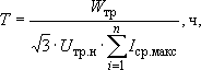 where Utr.n. - rated line-to-line voltage of the transformer on the low side. Based on the calculated values of T and τ, a graph of dependence τ = ƒ (T) can be plotted. Annual electricity losses in all transformers are determined by:
 ![]() where n is the number of transformers in the electrical network. Relative value of electricity losses in power transformers:
where n is the number of transformers in the electrical network. Relative value of electricity losses in power transformers: ![]() where Wtr is the amount of electricity supplied to power transformers, kW ∙ h: transformers, improvement of methods and means of their operation. Losses in transformers are determined by the number of hours of their operation, therefore, one of the conditions that ensure energy savings in transformers is to turn them off at low loads. This can be done if electrical installations intended for repair work, emergency lighting, etc., are supplied from one transformer at night.
where Wtr is the amount of electricity supplied to power transformers, kW ∙ h: transformers, improvement of methods and means of their operation. Losses in transformers are determined by the number of hours of their operation, therefore, one of the conditions that ensure energy savings in transformers is to turn them off at low loads. This can be done if electrical installations intended for repair work, emergency lighting, etc., are supplied from one transformer at night.
In power supply systems, they often resort to installing three-winding transformers to provide power to consumers at different voltages. The feasibility of their installation is explained by economic costs, which consist of the total investment and the cost of annual operating costs Ce, kt includes losses of electricity. The calculation of electricity losses is complicated by the fact that in the reference materials the power losses in three-winding transformers are given in total, provided that all three windings are loaded at 100% (high, medium and low voltages). In actual conditions, the load of the transformer windings does not have such a ratio. For example, when the load on the high voltage windings is 100%, the sum of the loads on the medium and low voltage windings should also be 100%. Thus, due to the fact that until now in the catalog data losses in the metal of the windings of three-winding transformers are given for simultaneous loading of 100% of each winding, the calculated losses for three-winding transformers are obtained not corresponding to the actual ones with an error in the direction of exceeding. As a result, erroneous decisions can be obtained, especially when economically comparing the use of a three-winding transformer and two two-winding ones for the corresponding voltages and powers. To correctly determine the power losses in three-winding transformers, use the expression
∆PT.T = ∆Pхх + ∆PО.У + k2g.HV ∆Pc.HV + k2g.CH ∆Pk.CH + k2g.NN ∆Pc.HN,
where ΔРХХ - no-load power losses of the transformer; ΔР0, у - power of cooling devices; ΔРkvn - power losses in the metal of "high voltage windings at 100" load; k3vn - load factor of the high voltage winding; ΔРКсн - power losses in the metal of the medium voltage winding at 100% load; k3сн - load factor of the medium voltage winding; ΔРКнн - power losses in the metal of the low voltage winding at 100% load; k3нн is the load factor of the low voltage winding. In this case, the expression is converted, as for two-winding transformers, to a form corresponding to the account of active power losses from the reactive load of the transformer, namely:
∆P'T.T = ∆P'x + ∆PO.Y + k2g.VN ∆P'k.VN + k2g.CH ∆P'k.CH + k2g.NN ∆P'k.NN
The value of ΔROU is taken into account for the time when the load of the transformer has a value greater than 70% of the rated power, i.e. when the cooling units are in operation.
Since the catalogs, factory data and other sources provide information about ΔРКвн, ΔРКсн and ΔРКнн, we give a method for their determination, based on the fact that in the initial technical data on three-winding transformers, power losses in the metal of the windings are set in pairs:
ΔРК int. nn - power losses in the high and low voltage windings; ΔРК vn _ SN - power losses in high and medium voltage windings; ΔРК sn. nn - power losses in the windings of medium and low voltage To determine the losses when each winding is loaded at the rated power of the transformer, we compose the equations
∆Pk, VN-CH = ∆Pk, VN + ∆Pk, CH
∆Pk, VN = (∆Pk, VN-CH + ∆Pk, VN-NN - ∆Pk, CH-CH) / 2
∆Pk, VN-LV = ∆Pk, VN + ∆Pk LV =>
∆Pk, CH = (∆Pk, VN-CH + ∆Pk, CH-NN - ∆Pk, VN-CH) / 2
∆Pк, СН-НН = ∆Pк, СН + ∆Pк, НН
∆Pk, VN = (∆Pk, VN-NN + ∆Pk, CH-NN - ∆Pk, VN-CH) / 2.
For use in further calculations, the values in the expressions must be converted to the given ones using kip. The data of these calculations are summarized in the table in the form of reduced losses. After determining the power losses, the cost of power losses should be determined.