a three-pin output connector to which the display power cable can be connected;
two-pin connector JP1, the mating part of which is located on the board.
From connector JP1, alternating mains voltage is supplied to:
bridge rectification circuit BR1 through thermistor THR1;
the primary winding of the starting transformer T1.
At the output of rectifier BR1, smoothing filter capacitances C1, C2 are included. The THR thermistor limits the initial surge of charging current for these capacitors. The 115V/230V SW switch provides the ability to power a switching power supply from both a 220-240V network and a 110/127V network.
High-ohm resistors R1, R2, shunt capacitors C1, C2 are baluns (equalize the voltages on C1 and C2), and also ensure the discharge of these capacitors after turning off the switching power supply from the network. The result of the operation of the input circuits is the appearance on the rectified mains voltage bus of a direct voltage Uep equal to +310V, with some ripples. This switching power supply uses a starting circuit with forced (external) excitation, which is implemented on a special starting transformer T1, on the secondary winding of which, after the power supply is turned on, an alternating voltage with the frequency of the supply network appears. This voltage is rectified by diodes D25, D26, which form a full-wave rectification circuit with a midpoint with the secondary winding T1. SZO is a smoothing filter capacitance on which a constant voltage is generated, used to power the control microcircuit U4.
The TL494 IC is traditionally used as a control chip in this switching power supply.
The supply voltage from the SZO capacitor is supplied to pin 12 of U4. As a result, the output voltage of the internal reference source Uref = -5B appears at pin 14 of U4, the internal sawtooth voltage generator of the microcircuit starts, and control voltages appear at pins 8 and 11, which are sequences rectangular pulses with negative leading edges, shifted relative to each other by half a period. Elements C29, R50 connected to pins 5 and 6 of the U4 microcircuit determine the frequency of the sawtooth voltage generated by the internal generator of the microcircuit.
The matching stage in this switching power supply is made according to a transistorless circuit with separate control. The supply voltage from the capacitor SZO is supplied to the middle points of the primary windings of control transformers T2, TZ. The output transistors of IC U4 perform the functions of matching stage transistors and are connected according to the circuit with the OE. The emitters of both transistors (pins 9 and 10 of the microcircuit) are connected to the “case”. The collector loads of these transistors are the primary half-windings of the control transformers T2, T3, connected to pins 8, 11 of the U4 microcircuit (open collectors of the output transistors). The other halves of the primary windings T2, T3 with diodes D22, D23 connected to them form demagnetization circuits for the cores of these transformers.
Transformers T2, TZ control powerful transistors of the half-bridge inverter.
Switching the output transistors of the microcircuit causes the appearance of pulsed control EMF on the secondary windings of control transformers T2, T3. Under the influence of these EMFs, power transistors Q1, Q2 alternately open with adjustable pauses (“dead zones”). Therefore, alternating current flows through the primary winding of the T5 power pulse transformer in the form of sawtooth current pulses. This is explained by the fact that the primary winding T5 is included in the diagonal of the electrical bridge, one arm of which is formed by transistors Q1, Q2, and the other by capacitors C1, C2. Therefore, when any of the transistors Q1, Q2 is opened, the primary winding T5 is connected to one of the capacitors C1 or C2, which causes current to flow through it as long as the transistor is open.
Damper diodes D1, D2 ensure the return of energy stored in the leakage inductance of the primary winding T5 during the closed state of transistors Q1, Q2 back to the source (recuperation).
Capacitor SZ, connected in series with the primary winding T5, eliminates the direct current component through the primary winding T5, thereby eliminating unwanted magnetization of its core.
Resistors R3, R4 and R5, R6 form basic dividers for powerful transistors Q1, Q2, respectively, and provide optimal switching mode from the point of view of dynamic power losses on these transistors.
The diodes of the SD2 assembly are diodes with a Schottky barrier, which achieves the required speed and increases the efficiency of the rectifier.
Winding III together with winding IV provides an output voltage of +12V together with the diode assembly (half bridge) SD1. This assembly forms, with winding III, a full-wave rectification circuit with a midpoint. However, the middle point of winding III is not grounded, but is connected to the +5V output voltage bus. This will make it possible to use Schottky diodes in the +12V generation channel, because the reverse voltage applied to the rectifier diodes with this connection is reduced to the permissible level for Schottky diodes.
Elements L1, C6, C7 form a smoothing filter in the +12V channel.
The middle point of winding II is grounded.
Stabilization of output voltages is carried out different ways in different channels.
Negative output voltages -5V and -12V are stabilized using linear integrated three-terminal stabilizers U4 (type 7905) and U2 (type 7912).
To do this, the output voltages of the rectifiers from capacitors C14, C15 are supplied to the inputs of these stabilizers. The output capacitors C16, C17 produce stabilized output voltages of -12V and -5V.
Diodes D7, D9 ensure the discharge of output capacitors C16, C17 through resistors R14, R15 after turning off the switching power supply from the network. Otherwise, these capacitors would be discharged through the stabilizer circuit, which is undesirable.
Through resistors R14, R15, capacitors C14, C15 are also discharged.
Diodes D5, D10 perform a protective function in the event of breakdown of the rectifier diodes.
The +12V output voltage in this UPS is not stabilized.
Adjustment of the output voltage level in this UPS is carried out only for the +5V and +12V channels. This adjustment is carried out by changing the level of the reference voltage at the direct input of the error amplifier DA3 using trimming resistor VR1.
When changing the position of the VR1 slider during the UPS setup process, the voltage level on the +5V bus will change within certain limits, and therefore on the +12V bus, because voltage from the +5V bus is supplied to the middle point of winding III.
The combined protection of this UPS includes:
Limiting circuit for controlling the width of control pulses;
complete circuit protection against short circuit in loads;
incomplete output overvoltage control circuit (only on the +5V bus).
Let's look at each of these schemes.
The limiting control circuit uses current transformer T4 as a sensor, the primary winding of which is connected in series with the primary winding of the power pulse transformer T5.
Resistor R42 is the load of the secondary winding T4, and diodes D20, D21 form a full-wave rectification circuit for alternating pulse voltage removed from load R42.
Resistors R59, R51 form a divider. Part of the voltage is smoothed out by capacitor C25. The voltage level on this capacitor proportionally depends on the width of the control pulses at the bases of power transistors Q1, Q2. This level is fed through resistor R44 to the inverting input of the error amplifier DA4 (pin 15 of the U4 chip). The direct input of this amplifier (pin 16) is grounded. Diodes D20, D21 are connected so that capacitor C25, when current flows through these diodes, is charged to a negative (relative to the common wire) voltage.
In normal operation, when the width of the control pulses does not exceed acceptable limits, the potential of pin 15 is positive, due to the connection of this pin through resistor R45 to the Uref bus. If the width of the control pulses increases excessively for any reason, the negative voltage on capacitor C25 increases and the potential of pin 15 becomes negative. This leads to the appearance of the output voltage of the error amplifier DA4, which was previously equal to 0V. A further increase in the width of the control pulses leads to the fact that the switching control of the PWM comparator DA2 is transferred to the amplifier DA4, and the subsequent increase in the width of the control pulses no longer occurs (limitation mode), because the width of these pulses no longer depends on the level of the feedback signal at the direct input of the error amplifier DA3.
The short circuit protection circuit in loads can be conditionally divided into protection of channels for generating positive voltages and protection of channels for generating negative voltages, which are implemented in approximately the same circuitry.
The sensor of the short-circuit protection circuit in the loads of channels generating positive voltages (+5V and +12V) is a diode-resistive divider D11, R17, connected between the output buses of these channels. The voltage level at the anode of diode D11 is a controlled signal. In normal operation, when the voltages on the output buses of the +5V and +12V channels have nominal values, the anode potential of diode D11 is about +5.8V, because through the divider-sensor current flows from the +12V bus to the +5V bus along the circuit: +12V bus - R17-D11 - +56 bus.
The controlled signal from the anode D11 is fed to the resistive divider R18, R19. Part of this voltage is removed from resistor R19 and supplied to the direct input of comparator 1 of the U3 microcircuit of the LM339N type. The inverting input of this comparator is supplied with a reference voltage level from resistor R27 of the divider R26, R27 connected to the output of the reference source Uref=+5B of the control chip U4. The reference level is selected such that, during normal operation, the potential of the direct input of comparator 1 would exceed the potential of the inverse input. Then the output transistor of comparator 1 is closed, and the UPS circuit operates normally in PWM mode.
In the case of a short circuit in the load of the +12V channel, for example, the anode potential of diode D11 becomes equal to 0V, so the potential of the inverting input of comparator 1 will become higher than the potential of the direct input, and the output transistor of the comparator will open. This will cause the closing of transistor Q4, which is normally open by the base current flowing through the circuit: Upom bus - R39 - R36 - b-e Q4 - “case”.
Turning on the output transistor of comparator 1 connects resistor R39 to the "case" and therefore transistor Q4 is passively turned off by zero bias. Closing transistor Q4 entails charging capacitor C22, which serves as a delay element for the protection. The delay is necessary for the reasons that when the UPS enters mode, the output voltages on the +5V and +12V buses do not appear immediately, but as the output capacitors charge large capacity. The reference voltage from the source Uref, on the contrary, appears almost immediately after the UPS is connected to the network. Therefore, in the starting mode, comparator 1 switches, its output transistor opens, and if the delay capacitor C22 were missing, this would lead to the protection triggering immediately when the UPS is turned on to the network. However, C22 is included in the circuit, and the protection operates only after the voltage on it reaches the level determined by the values of resistors R37, R58 of the divider connected to the Upom bus and which is the base for transistor Q5. When this happens, transistor Q5 opens, and resistor R30 is connected through the low internal resistance of this transistor to the “case”. Therefore, a path appears for the base current of transistor Q6 to flow through the circuit: Uref - e-6 Q6 - R30 - e-e Q5 - “case”.
Transistor Q6 is opened by this current until saturation, as a result of which the voltage Uref = 5B, which powers transistor Q6 along the emitter, is applied through its low internal resistance to pin 4 of the control chip U4. This, as was shown earlier, leads to the stop of the digital path of the microcircuit, the disappearance of output control pulses and the cessation of switching of power transistors Q1, Q2, i.e. to protective shutdown. A short circuit in the +5V channel load will result in the anode potential of diode D11 being only about +0.8V. Therefore, the output transistor of the comparator (1) will be open, and a protective shutdown will occur.
In a similar way, short-circuit protection is built in the loads of channels generating negative voltages (-5V and -12V) on comparator 2 of the U3 chip. Elements D12, R20 form a diode-resistive divider-sensor, connected between the output buses of the negative voltage generation channels. The controlled signal is the cathode potential of diode D12. During a short circuit in a -5V or -12V channel load, the potential of cathode D12 increases (from -5.8 to 0V for a short circuit in a -12V channel load and to -0.8V for a short circuit in a -5V channel load). In any of these cases, the normally closed output transistor of comparator 2 opens, which causes the protection to operate according to the above mechanism. In this case, the reference level from resistor R27 is supplied to the direct input of comparator 2, and the potential of the inverting input is determined by the values of resistors R22, R21. These resistors form a bipolarly powered divider (resistor R22 is connected to the bus Uref = +5V, and resistor R21 is connected to the cathode of diode D12, the potential of which in normal operation of the UPS, as already noted, is -5.8V). Therefore, the potential of the inverting input of comparator 2 in normal operation is maintained lower than the potential of the direct input, and the output transistor of the comparator will be closed.
Protection against output overvoltage on the +5V bus is implemented on elements ZD1, D19, R38, C23. Zener diode ZD1 (with a breakdown voltage of 5.1V) is connected to the +5V output voltage bus. Therefore, as long as the voltage on this bus does not exceed +5.1 V, the zener diode is closed, and transistor Q5 is also closed. If the voltage on the +5V bus increases above +5.1V, the zener diode “breaks through”, and an unlocking current flows into the base of transistor Q5, which leads to the opening of transistor Q6 and the appearance of voltage Uref = +5V at pin 4 of the control chip U4, i.e. . to protective shutdown. Resistor R38 is a ballast for the zener diode ZD1. Capacitor C23 prevents the protection from triggering during random short-term voltage surges on the +5V bus (for example, as a result of the voltage settling after a sudden decrease in the load current). Diode D19 is a decoupling diode.
The PG signal generation circuit in this switching power supply is dual-functional and is assembled on comparators (3) and (4) of the U3 microcircuit and transistor Q3.
The circuit is built on the principle of monitoring the presence of alternating low-frequency voltage on the secondary winding of the starting transformer T1, which acts on this winding only if there is a supply voltage on the primary winding T1, i.e. while the switching power supply is connected to the mains.
Almost immediately after the UPS is turned on, the auxiliary voltage Upom appears on the capacitor SZO, which powers the control microcircuit U4 and the auxiliary microcircuit U3. In addition, the alternating voltage from the secondary winding of the starting transformer T1 through diode D13 and current-limiting resistor R23 charges capacitor C19. The voltage from C19 powers the resistive divider R24, R25. From resistor R25, part of this voltage is supplied to the direct input of comparator 3, which leads to the closing of its output transistor. The output voltage of the internal reference source of the microcircuit U4 Uref = +5B, which appears immediately after this, powers the divider R26, R27. Therefore, the reference level from resistor R27 is supplied to the inverting input of comparator 3. However, this level is chosen to be lower than the level at the direct input, and therefore the output transistor of comparator 3 remains in the off state. Therefore, the process of charging the holding capacity C20 begins along the chain: Upom - R39 - R30 - C20 - “housing”.
The voltage, which increases as capacitor C20 charges, is supplied to the inverse input 4 of the U3 microcircuit. The direct input of this comparator is supplied with voltage from resistor R32 of the divider R31, R32 connected to the Upom bus. As long as the voltage across the charging capacitor C20 does not exceed the voltage across resistor R32, the output transistor of comparator 4 is closed. Therefore, an opening current flows into the base of transistor Q3 through the circuit: Upom - R33 - R34 - 6th Q3 - “case”.
Transistor Q3 is open to saturation, and the PG signal taken from its collector has a passive low level and prohibits the processor from starting. During this time, during which the voltage level on capacitor C20 reaches the level on resistor R32, the switching power supply manages to reliably enter the nominal operating mode, i.e. all its output voltages appear in full.
As soon as the voltage on C20 exceeds the voltage removed from R32, comparator 4 will switch and its output transistor will open.
This will cause transistor Q3 to close, and the PG signal taken from its collector load R35 becomes active (H-level) and allows the processor to start.
When the switching power supply is turned off from the network, the alternating voltage disappears on the secondary winding of the starting transformer T1. Therefore, the voltage on capacitor C19 quickly decreases due to the small capacitance of the latter (1 µF). As soon as the voltage drop across resistor R25 becomes less than that across resistor R27, comparator 3 will switch and its output transistor will open. This will entail a protective shutdown of the output voltages of the control chip U4, because transistor Q4 will open. In addition, through the open output transistor of comparator 3, the process of accelerated discharge of capacitor C20 will begin along the circuit: (+)C20 - R61 - D14 - k-e day off comparator transistor 3 - “case”.
As soon as the voltage level at C20 becomes less than the voltage level at R32, comparator 4 will switch and its output transistor will close. This will cause transistor Q3 to open and the PG signal to go to an inactive low level before the voltages on the UPS output buses begin to decrease unacceptably. This will initialize the signal system reset computer and original state the entire digital part of the computer.
Both comparators 3 and 4 of the PG signal generation circuit are covered by positive feedback using resistors R28 and R60, respectively, which speeds up their switching.
A smooth transition to mode in this UPS is traditionally ensured using the forming chain C24, R41, connected to pin 4 of the control chip U4. The residual voltage at pin 4, which determines the maximum possible duration of the output pulses, is set by the divider R49, R41.
The fan motor is powered by voltage from capacitor C14 in the -12V voltage generation channel through an additional decoupling L-shaped filter R16, C15.
Any computer cannot operate without a power supply. Therefore, you should take your choice seriously. After all, the performance of the computer itself will depend on the stable and reliable operation of the power supply.
What it is
The main task of the power supply is to convert alternating current and further generate the required voltage for the normal operation of all PC components.
Voltage required for operation of components:
- +12V;
- +3.3V.
In addition to these declared values, there are additional values:
- -12V;
The power supply acts as a galvanic isolation between electric shock from the socket and components consuming current. A simple example: if a current leak occurs and a person touches the housing system unit he would get an electric shock, but thanks to the power supply this does not happen. ATX format power supplies (PS) are often used.
Overview of power supply circuits
The main part block diagram The IP, ATX format, is a half-bridge converter. The operation of converters of this type is to use push-pull mode.
Stabilization of the output parameters of the IP is carried out using pulse-width modulation (PWM controller) of control signals.
Switching power supplies often use the TL494 PWM controller chip, which has a number of positive properties:
- acceptable performance characteristics of the microcircuit. This is a low starting current, speed;
- presence of universal internal protection elements;
- Ease of use.
Simple switching power supply
Operating principle of conventional pulse The power supply can be seen in the photo.

The first block performs the change from alternating current to direct current. The converter is made in the form of a diode bridge, which converts voltage, and a capacitor, which smoothes out oscillations.
In addition to these elements, additional components may be present: a voltage filter and thermistors. But, due to the high cost, these components may not be available.
The generator creates pulses with a certain frequency that power the transformer winding. The transformer performs the main work in the power supply; this is galvanic isolation and conversion of current to the required values.
Video: Operating principle of the PWM controller
ATX without coefficient correction
A simple switching power supply, although a working device, is inconvenient to use in practice. Many of its output parameters “float”, including voltage. All these indicators change due to unstable voltage, temperature and load on the converter output.
But if you control these indicators using a controller that will act as a stabilizer and additional functions, then the circuit will be quite suitable for use.
The block diagram of a power supply using a pulse-width modulation controller is simple and represents a pulse generator on a PWM controller.

The PWM controller regulates the amplitude of changes in signals passing through the filter low frequencies(LPF). The main advantage is the high efficiency of power amplifiers and ample opportunities in use.
ATX with power factor correction
In new power supplies for PCs, an additional unit appears - a power factor corrector (PFC). The PFC eliminates the emerging errors of the AC bridge rectifier and increases the power factor (PF).
Therefore, manufacturers are actively producing power supplies with mandatory CM correction. This means that the power supply on the computer will operate in the range of 300W or more.

These power supplies use a special inductor with an inductance higher than that at the input. Such an IP is called PFC or passive PFC. It has an impressive weight due to the additional use of capacitors at the rectifier output.
Disadvantages include the low reliability of the power supply and incorrect operation of the UPS when switching the “battery/mains” operating mode.
This is due to the small capacity of the mains voltage filter and at the moment the voltage drops, the PFC current increases, and at this moment the short circuit protection is activated.
On a two-channel PWM controller
Dual-channel PWM controllers are often used in modern computer power supplies. A single microcircuit is capable of performing the role of a converter and CM corrector, which reduces the total number of elements in the power supply circuit.
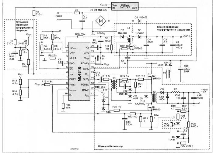
In the above circuit, the first part generates a stabilized voltage of +38V, and the second part is a converter that generates a stabilized voltage of +12V.
Computer power supply connection diagram
To connect the power supply to the computer, you must perform a series of sequential steps:

Design features
To connect components personal computer The power supply has various connectors. On the back of it there is a connector for the network cable and a switch button.
In addition, there may also be a connector for connecting a monitor on the back wall of the power supply.
Different models may have other connectors:

In modern PC power supplies, it is less common to install a fan on the rear wall, which draws hot air from the power supply. To replace this solution, they began to use a fan on the top wall, which was larger and quieter.
On some models it is possible to find two fans at once. From the wall, which is located inside the system unit, comes a wire with a special connector for supplying current to the motherboard. The photo shows possible connection connectors and contact designations.

Each wire color supplies a specific voltage:
- yellow - +12 V;
- red - +5 V;
- orange - +3.3 V;
- black – grounding.
U various manufacturers Values for these wire colors may vary.
There are also connectors for supplying current to computer components.

Parameters and characteristics
The power supply unit of a personal computer has many parameters that may not be indicated in the documentation. Several parameters are indicated on the side label - voltage and power.
Power is the main indicator
This information is written on the label in large print. The power rating of a power supply indicates the total amount of electricity available to internal components.
It would seem that choosing a power supply with the required power would be enough to sum up the consumed indicators of the components and select a power supply with a small margin. Therefore, there will not be a big difference between 200w and 250w.

But in reality the situation looks more complicated, because the output voltage can be different - +12V, -12V and others. Each voltage line consumes a certain amount of power. But in the power supply there is one transformer that generates all the voltages used by the PC. In rare cases, two transformers may be placed. This is an expensive option and is used as a source on servers.
In simple power supplies, 1 transformer is used. Because of this, the power on the voltage lines can change, increase with low load on other lines, and vice versa decrease.
Operating voltage
When choosing a power supply, you should pay attention to the maximum operating voltage values, as well as the range of incoming voltages; it should be from 110V to 220V.
True, most users do not pay attention to this and when choosing a power supply with ratings from 220V to 240V they risk frequent PC shutdowns.

Such a power supply will turn off when the voltage drops, which is not uncommon for our electrical networks. Exceeding the declared values will lead to the PC turning off and the protection will work. To turn the power supply back on, you will have to disconnect it from the network and wait a minute.
It should be remembered that the processor and video card consume a maximum operating voltage of 12V. Therefore, you should pay attention to these indicators. To reduce the load on the connectors, the 12V line is divided into a parallel pair with the designation +12V1 and +12V2. These indicators must be indicated on the label.
Before choosing a power supply for purchase, you should pay attention to the power consumption of the internal components of the PC.
But some video cards require a special current consumption of +12V and these indicators should be taken into account when choosing a power supply. Typically, for a PC with one video card installed, a source with a power of 500 W or 600 is sufficient.

You should also read customer reviews and expert reviews about the selected model and the manufacturer. Best options The things you should pay attention to are: power, quiet operation, quality and compliance with the written characteristics on the label.
There is no need to save money, because the operation of the entire PC will depend on the operation of the power supply. Therefore, the better and more reliable the source, the longer the computer will last. The user can be sure that he has done right choice and don’t worry about sudden shutdowns of your PC.
ATX POWER SUPPLY, CIRCUIT
Every day they become more and more popular among radio amateurs. computer blocks nutritionATX. At a relatively low price, they represent a powerful, compact voltage source of 5 and 12 V 250 - 500 watts. BPATXcan also be used in chargers for car batteries, and laboratory blocks nutrition, and welding inverters, and many more applications can be found for them with a certain amount of imagination. Moreover, if the power supply circuitATXand is subject to alteration, then minimal.
The circuit design of these power supplies is approximately the same for almost all manufacturers. A small difference applies only to AT and ATX power supplies. The main difference between them is that the AT power supply does not support the advanced power management standard in software. You can turn off this power supply only by stopping the supply of voltage to its input, and in ATX power supplies it is possible to programmatically turn it off using a control signal from the motherboard. Usually ATX board has larger dimensions than AT and is elongated vertically.
In any computer power supply, the +12 V voltage is intended to power the disk drive motors. The power supply for this circuit must provide a large output current, especially in computers with many drive bays. This voltage is also supplied to the fans. They consume current up to 0.3 A, but in new computers this value is below 0.1 A. +5 volt power is supplied to all components of the computer, therefore it has very high power and current, up to 20 A, and the +3.3 volt voltage is intended exclusively for powering the processor. Knowing that modern multi-core processors have a power of up to 150 watts, it is easy to calculate the current of this circuit: 100 watts/3.3 volts = 30 A! Negative voltages -5 and -12 V are ten times weaker than the main positive ones, so there are simple 2-amp diodes without radiators.
The tasks of the power supply also include suspending the functioning of the system until the input voltage reaches a value sufficient for normal operation. Each power supply undergoes internal checks and output voltage testing before being allowed to start the system. After this, a special Power Good signal is sent to the motherboard. If this signal is not received, the computer will not work.

The Power Good signal can be used for manual reset if applied to the clock generator chip. When the Power Good signal circuit is grounded, clock generation stops and the processor stops. After opening the switch, a short-term processor initialization signal is generated and normal signal flow is allowed - a hardware reboot of the computer is performed. In computer power supplies of the ATX type, there is a signal called PS ON; it can be used by the program to turn off the power source.
Here you can download computer power supplies, and here is a very useful description, types and principle of operation of AT and ATX power supplies.To check the functionality of the power supply, you should load the power supply with lamps for car headlights and measure all output voltages with a tester. If the voltage is within normal limits. It is also worth checking the change in the voltage supplied by the power supply with a change in load.
The operation of these power supplies is very stable and reliable, but in the event of combustion, powerful transistors, low-resistance resistors, rectifier diodes on the radiator, varistors, transformer and fuse most often fail.
For computer power supplies
Circuitry of computer power supplies
Circuits for computers
R. ALEXANDROV, Maloyaroslavets, Kaluga region.
Radio, 2002, No. 5, 6, 8
UPSs of household computers are designed to operate from a single-phase alternating current network (110/230 V, 60 Hz ≈ imported, 127/220 V, 50 Hz ≈ domestic production). Since the 220 V, 50 Hz network is generally accepted in Russia, the problem of choosing a unit for the required mains voltage does not exist. You just need to make sure that the mains voltage switch on the unit (if there is one) is set to 220 or 230 V. The absence of a switch indicates that the unit is capable of operating in the mains voltage range indicated on its label without any switching. UPSs designed for 60 Hz operate flawlessly on a 50 Hz network.
The UPS is connected to AT format motherboards with two wire harnesses with sockets P8 and P9, shown in Fig. 1 (view from the side of the nests). The wire colors indicated in brackets are standard, although not all UPS manufacturers strictly adhere to them. To properly orient the sockets when connecting to the motherboard plugs, there is a simple rule: the four black wires (GND circuit) going to both sockets must be located next to each other.
The main power circuits of ATX format motherboards are concentrated in the connector shown in Fig. 2. As in the previous case, view from the side of the sockets. UPSs of this format have an input remote control(PS-ON circuit), when connected to a common wire (COM circuit ≈ "common", equivalent to GND), the unit connected to the network begins to work. If the PS-ON≈COM circuit is open, there is no voltage at the UPS outputs, with the exception of the “standby” +5 V in the +5VSB circuit. In this mode, the power consumed from the network is very low.

ATX format UPSs are equipped with an additional output socket, shown in Fig. 3. The purpose of its circuits is as follows:
FanM ≈ output of the fan rotation speed sensor cooling the UPS (two pulses per revolution);
FanC ≈ analog (0...12 V) input for controlling the rotation speed of this fan. If this input is disconnected from external circuits or a constant voltage of more than 10 V is applied to it, the fan performance is maximum;
3.3V Sense ≈ feedback signal input of the voltage stabilizer +3.3 V. It is connected with a separate wire directly to the power pins of the microcircuits on the system board, which allows you to compensate for the voltage drop on the supply wires. If there is no additional socket, this circuit can be routed to socket 11 of the main socket (see Fig. 2);
1394R ≈ minus of an 8...48 V voltage source isolated from the common wire to power the IEEE-1394 interface circuits;
1394V ≈ plus of the same source.
A UPS of any format must be equipped with several sockets to power disk drives and some other computer peripherals.

Every "computer" UPS outputs a logical signal called R G. (Power Good) in AT blocks or PW-OK (Power OK) in ATX blocks, high level which indicates that all output voltages are within acceptable limits. On the “motherboard” of the computer, this signal is involved in generating the system reset signal. After turning on the UPS, the RG signal level. (PW-OK) remains low for some time, prohibiting the processor from operating until the transient processes in the power circuits are completed.
When the mains voltage is turned off or the UPS suddenly malfunctions, the logical level of the P.G. signal (PW-OK) changes before the unit’s output voltages drop below permissible values. This causes the processor to stop, prevents corruption of data stored in memory and other irreversible operations.
The interchangeability of a UPS can be assessed using the following criteria.
Number of output voltages to power an IBM PC AT format there must be at least four (+12 V, +5 V, -5 V and -12 V). The maximum and minimum output currents are regulated separately for each channel. Their usual values for sources of various powers are given in table. 1 . ATX computers additionally require +3.3 V and some other voltages (they were mentioned above).

Please note that normal operation block operation at a load less than the minimum is not guaranteed, and sometimes this mode is simply dangerous. Therefore, it is not recommended to connect the UPS without load to the network (for example, for testing).
The power of the power supply (total for all output voltages) in a household PC fully equipped with peripheral devices must be at least 200 W. It is practically necessary to have 230...250 W, and when installing additional hard drives and CD-ROM drives, more may be required. PC malfunctions, especially those that occur when the electric motors of the mentioned devices are turned on, are often associated with an overload of the power supply. Computers used as information network servers consume up to 350 W. Low-power UPSs (40...160 W) are used in specialized, for example, control computers with a limited set of peripherals.
The volume occupied by a UPS usually increases due to an increase in its length towards the front panel of the PC. The installation dimensions and mounting points of the unit in the computer case remain unchanged. Therefore, any (with rare exceptions) block can be installed in the place of the failed one.
The basis of most UPSs is a push-pull half-bridge inverter operating at a frequency of several tens of kilohertz. The inverter supply voltage (approximately 300 V) is rectified and smoothed mains voltage. The inverter itself consists of a control unit (pulse generator with an intermediate power amplification stage) and a powerful output stage. The latter is loaded onto a high-frequency power transformer. The output voltages are obtained using rectifiers connected to the secondary windings of this transformer. Voltage stabilization is carried out using pulse width modulation (PWM) of pulses generated by the inverter. Typically, only one output channel is covered by the stabilizing OS, usually +5 or +3.3 V. As a result, the voltages at other outputs do not depend on the network voltage, but remain subject to the influence of the load. Sometimes they are additionally stabilized using conventional stabilizer chips.
MAINS RECTIFIER

In most cases, this unit is performed according to a scheme similar to that shown in Fig. 4, the differences are only in the type of rectifier bridge VD1 and a greater or lesser number of protective and safety elements. Sometimes the bridge is assembled from individual diodes. When switch S1 is open, which corresponds to the unit being powered from a 220...230 V network, the rectifier is a bridge, the voltage at its output (capacitors C4, C5 connected in series) is close to the amplitude of the network. When powered from a network of 110... 127 V, by closing the contacts of the switch, they turn the device into a rectifier with doubling the voltage and obtain at its output a constant voltage that is twice the amplitude of the network voltage. Such switching is provided in UPSs, the stabilizers of which keep the output voltages within acceptable limits only when the mains voltage deviates by 20%. Units with more effective stabilization are able to operate at any mains voltage (usually from 90 to 260 V) without switching.
Resistors R1, R4 and R5 are designed to discharge the rectifier capacitors after it is disconnected from the network, and C4 and C5, in addition, equalize the voltages on capacitors C4 and C5. Thermistor R2 with a negative temperature coefficient limits the amplitude of the inrush current charging capacitors C4, C5 at the moment the unit is turned on. Then, as a result of self-heating, its resistance drops, and it practically does not affect the operation of the rectifier. Varistor R3 with a classification voltage greater than the maximum amplitude of the network protects against surges of the latter. Unfortunately, this varistor is useless if a unit with a closed switch S1 is accidentally turned on in a 220 V network. The serious consequences of this can be avoided by replacing resistors R4, R5 with varistors with a classification voltage of 180...220 V, the breakdown of which entails the combustion of the fuse-link FU1. Sometimes varistors are connected in parallel with the specified resistors or only one of them.
Capacitors C1 ≈ SZ and two-winding inductor L1 form a filter that protects the computer from interference from the network, and the network from interference, computer generated. Through capacitors C1 and SZ, the computer case is connected via alternating current to the network wires. Therefore, the voltage of touching an ungrounded computer can reach half the network voltage. This is not life-threatening, since the reactance of the capacitors is quite high, but it often leads to failure of the interface circuits when peripheral devices are connected to the computer.
POWERFUL INVERTER CASCADE

On rice. 5 shows part of the circuit diagram of the common GT-150W UPS. The pulses generated by the control unit are sent through transformer T1 to the bases of transistors VT1 and VT2, opening them alternately. Diodes VD4, VD5 protect transistors from reverse polarity voltage. Capacitors C6 and C7 correspond to C4 and C5 in the rectifier (see Fig. 4). The voltages of the secondary windings of transformer T2 are rectified to obtain output. One of the rectifiers (VD6, VD7 with filter L1C5) is shown in the diagram.
Most powerful UPS cascades differ from those considered only in the types of transistors, which can be, for example, field-effect ones or contain built-in protective diodes. There are several options for the design of basic circuits (for bipolar) or gate circuits (for field-effect transistors) with different numbers, ratings and circuits for connecting elements. For example, resistors R4, R6 can be connected directly to the bases of the corresponding transistors.
In steady state, the inverter control unit is supplied with the output voltage of the UPS, but at the moment of switching on it is absent. There are two main ways to obtain the supply voltage necessary to start the inverter. The first of them is implemented in the scheme under consideration (Fig. 5). Immediately after turning on the unit, the rectified mains voltage flows through the resistive divider R3 ≈ R6 into the base circuits of transistors VT1 and/T2, opening them slightly, and diodes VD1 and VD2 prevent the base-emitter sections of the transistors from being shunted by windings II and III of transformer T1. At the same time, capacitors C4, C6 and C7 are charged, and the charging current of capacitor C4, flowing through winding I of transformer T2 and through part of winding II of transformer T1, induces a voltage in windings II and III of the latter that opens one of the transistors and closes the other. Which transistor will close and which will open depends on the asymmetry of the characteristics of the cascade elements.
As a result of the action of positive feedback, the process proceeds like an avalanche, and a pulse induced in winding II of transformer T2 through one of the diodes VD6, VD7, resistor R9 and diode VD3 charges the capacitor SZ to a voltage sufficient to start operation of the control unit. Subsequently, it is powered by the same circuit, and the voltage rectified by diodes VD6, VD7, after smoothing by the L1C5 filter, is supplied to the +12 V output of the UPS.
The version of the initial startup circuits used in the LPS-02-150XT UPS differs only in that the voltage to the divider, similar to R3 ≈ R6 (Fig. 5), is supplied from a separate half-wave rectifier of the mains voltage with a small-capacity filter capacitor. As a result, the inverter transistors open slightly before the main rectifier filter capacitors (C6, C7, see Fig. 5) are charged, which ensures a more reliable start.
The second method of powering the control unit during startup involves the presence of a special low-power step-down transformer with a rectifier, as shown in the diagram in Fig. 6 used in the PS-200B UPS.

The number of turns of the secondary winding of the transformer is selected so that the rectified voltage is slightly less than the output in the +12 V channel of the unit, but sufficient for the operation of the control unit. When the output voltage of the UPS reaches its nominal value, the diode VD5 opens, the diodes of the bridge VD1 ≈ VD4 remain closed during the entire period of alternating voltage and the control unit switches to power supply with the output voltage of the inverter, without consuming more energy from the “starting” transformer.
In high-power inverter stages triggered in this way, there is no need for an initial bias at the bases of the transistors and positive feedback. Therefore, resistors R3, R5 are not required, diodes VD1, VD2 are replaced with jumpers, and winding II of transformer T1 is made without a tap (see Fig. 5).
OUTPUT RECTIFIERS
In Fig. Figure 7 shows a typical diagram of a four-channel UPS rectifier unit. In order not to violate the symmetry of the magnetization reversal of the magnetic circuit power transformer rectifiers are built only using full-wave circuits, and bridge rectifiers, which are characterized by increased losses, are almost never used. The main feature of rectifiers in UPSs is smoothing filters, starting with inductance (choke). The voltage at the output of a rectifier with such a filter depends not only on the amplitude, but also on the duty cycle (the ratio of the duration to the repetition period) of the pulses arriving at the input. This makes it possible to stabilize the output voltage by changing the duty cycle of the input. Rectifiers with filters starting with a capacitor, used in many other cases, do not have this property. The process of changing the duty cycle of pulses is usually called PWM ≈ pulse width modulation(English PWM ≈ Pulse Width Modulation).
![]()
Since the amplitude of the pulses, proportional to the voltage in the supply network, at the inputs of all rectifiers in the block changes according to the same law, stabilizing one of the output voltages using PWM stabilizes all the others. To enhance this effect, filter chokes L1.1 ≈ L1.4 of all rectifiers are wound on a common magnetic core. The magnetic connection between them additionally synchronizes the processes occurring in the rectifiers.
For proper operation of a rectifier with an L-filter, it is necessary that its load current exceed a certain minimum value, depending on the inductance of the filter choke and the pulse frequency. This initial load is created by resistors R4 ≈ R7, connected in parallel with the output capacitors C5 ≈ C8. They also serve to speed up the discharge of capacitors after the UPS is turned off.
Sometimes a voltage of -5 V is obtained without a separate rectifier from a voltage of -12 V using an integrated stabilizer of the 7905 series. Domestic analogues are microcircuits KR1162EN5A, KR1179EN05. The current consumed by computer nodes along this circuit usually does not exceed several hundred milliamps.
In some cases, integrated stabilizers are installed in other UPS channels. This solution eliminates the influence of a changing load on the output voltages, but reduces the efficiency of the unit and for this reason is used only in relatively low-power channels. An example is the diagram of the PS-6220C UPS rectifier assembly shown in rice. 8. Diodes VD7 ≈ VD10 ≈ protective.

As in most other units, the +5 V voltage rectifier here contains Schottky barrier diodes (VD6 assembly), which are characterized by a lower forward voltage drop and reverse resistance recovery time than conventional diodes. Both of these factors are favorable for increasing efficiency. Unfortunately, the relatively low permissible reverse voltage does not allow the use of Schottky diodes in the +12 V channel. However, in the unit under consideration, this problem is solved by connecting two rectifiers in series: the missing 7 V is added to the 5 V by a rectifier on the Schottky diode assembly VD5.
To eliminate voltage surges that are dangerous for diodes and occur in the transformer windings at pulse fronts, damping circuits R1C1, R2C2, R3C3 and R4C4 are provided.
CONTROL UNIT
In most “computer” UPSs, this unit is built on the basis of the TL494CN PWM controller chip (domestic equivalent ≈ KR1114EU4) or its modifications. The main part of the diagram of such a node is shown in Fig. 9, it also shows the elements internal device the mentioned microcircuit.

The sawtooth voltage generator G1 serves as a master. Its frequency depends on the ratings external elements R8 and NW. The generated voltage is supplied to two comparators (A3 and A4), the output pulses of which are summed by the OR element D1. Next, the pulses through the NOR elements D5 and D6 are supplied to the output transistors of the microcircuit (V3, V4). Pulses from the output of element D1 also arrive at the counting input of trigger D2, and each of them changes the state of the trigger. Thus, if a log is applied to pin 13 of the microcircuit. 1 or, as in the case under consideration, it is left free, the pulses at the outputs of elements D5 and D6 alternate, which is necessary to control a push-pull inverter. If the TL494 chip is used in a single-ended voltage converter, pin 13 is connected to the common wire, as a result, trigger D2 is no longer involved in the operation, and pulses appear at all outputs simultaneously.
Element A1 is an error signal amplifier in the UPS output voltage stabilization circuit. This voltage (in this case ≈ +5 V) is supplied to one of the amplifier inputs through a resistive divider R1R2. At its second input ≈ the reference voltage obtained from the stabilizer A5 built into the chip using a resistive divider R3 ≈ R5. The voltage at output A1, proportional to the difference between the input ones, sets the operating threshold of comparator A4 and, consequently, the duty cycle of the pulses at its output. Since the output voltage of the UPS depends on the duty cycle (see above), in a closed system it is automatically maintained equal to the exemplary voltage, taking into account the division coefficient R1R2. The R7C2 chain is necessary for the stability of the stabilizer. The second amplifier (A2), in this case, from the switches by supplying the appropriate voltages to its inputs, does not participate in the operation.
The function of comparator A3 is to guarantee the presence of a pause between pulses at the output of element D1, even if the output voltage of amplifier A1 is outside the permissible limits. The minimum response threshold A3 (when connecting pin 4 to common) is set by the internal voltage source GV1. As the voltage at pin 4 increases, the minimum pause duration increases, therefore, the maximum output voltage of the UPS drops.
This property is used for smooth startup of the UPS. The fact is that at the initial moment of operation of the unit, the filter capacitors of its rectifiers are completely discharged, which is equivalent to shorting the outputs to the common wire. Starting the inverter immediately “at full power” will lead to a huge overload of the transistors of the powerful cascade and their possible failure. Circuit C1R6 ensures a smooth, overload-free start of the inverter.
At the first moment after switching on, capacitor C1 is discharged, and the voltage at pin 4 of DA1 is close to +5 V received from stabilizer A5. This guarantees a pause of the maximum possible duration, up to the complete absence of pulses at the output of the microcircuit. As capacitor C1 charges through resistor R6, the voltage at pin 4 decreases, and with it the duration of the pause. At the same time, the output voltage of the UPS increases. This continues until it approaches the exemplary one and the stabilizing effect comes into effect. Feedback. Further charging of capacitor C1 does not affect the processes in the UPS. Since capacitor C1 must be completely discharged before each UPS is turned on, in many cases circuits for its forced discharge are provided (not shown in Fig. 9).
INTERMEDIATE CASCADE

The task of this cascade is to amplify the pulses before feeding them to powerful transistors. Sometimes the intermediate stage is missing as an independent unit, being part of the master oscillator microcircuit. The diagram of such a cascade used in the PS-200B UPS is shown in Fig. 10 . Matching transformer T1 here corresponds to the one of the same name in Fig. 5.
The APPIS UPS uses an intermediate stage according to the circuit shown in Fig. 11, which differs from the one discussed above by the presence of two matching transformers T1 and T2 ≈ separately for each powerful transistor. The polarity of the transformer windings is such that the intermediate stage transistor and the power transistor associated with it are in the open state at the same time. If special measures are not taken, after a few cycles of inverter operation, the accumulation of energy in the magnetic circuits of the transformers will lead to saturation of the latter and a significant decrease in the inductance of the windings.
Let's consider how this problem is solved, using the example of one of the “halves” of the intermediate stage with transformer T1. When the transistor of the microcircuit is open, winding Ia is connected to the power source and the common wire. A linearly increasing current flows through it. A positive voltage is induced in winding II, which enters the base circuit of the powerful transistor and opens it. When the transistor in the microcircuit is closed, the current in winding Ia will be interrupted. But the magnetic flux in the magnetic core of the transformer cannot change instantly, so a linearly decreasing current will appear in winding Ib, flowing through the opened diode VD1 from the common wire to the plus of the power source. Thus, the energy accumulated in the magnetic field during the pulse returns to the source during the pause. The voltage on winding II during the pause is negative, and the powerful transistor is closed. The second “half” of the cascade with transformer T2 operates in a similar way, but in antiphase.
The presence of pulsating magnetic fluxes with a constant component in magnetic circuits leads to the need to increase the mass and volume of transformers T1 and T2. In general, an intermediate stage with two transformers is not very successful, although it has become quite widespread.

If the power of the transistors of the TL494CN microcircuit is not enough to directly control the output stage of the inverter, use a circuit similar to that shown in Fig. 12, which shows the intermediate stage of the KYP-150W UPS. The halves of winding I of transformer T1 serve as collector loads of transistors VT1 and VT2, alternately opened by pulses coming from the DA1 microcircuit. Resistor R5 limits the collector current of the transistors to approximately 20 mA. Using diodes VD1, VD2 and capacitor C1 on the emitters of transistors VT1 and VT2, the voltage required for their reliable closing is +1.6 V. Diodes VD4 and VD5 dampen the oscillations that occur when switching transistors in the circuit formed by the inductance of winding I of transformer T1 and its own capacity. Diode VD3 closes if the voltage surge at the middle terminal of winding I exceeds the cascade supply voltage.

Another version of the intermediate stage circuit (UPS ESP-1003R) is shown in Fig. 13. In this case, the output transistors of the DA1 microcircuit are connected according to a circuit with a common collector. Capacitors C1 and C2 are boosting. Winding I of transformer T1 does not have a middle terminal. Depending on which of the transistors VT1, VT2 in this moment is open, the winding circuit is closed to the power source through resistor R7 or R8 connected to the collector of the closed transistor.
TROUBLESHOOTING
Before repairing the UPS, it must be removed from the computer system unit. To do this, disconnect the computer from the network by removing the plug from the outlet. Having opened the computer case, release all the UPS connectors and, by unscrewing the four screws on the back wall of the system unit, remove the UPS. Then remove the U-shaped cover of the UPS case by unscrewing the screws securing it. printed circuit board can be removed by unscrewing the three self-tapping screws that secure it. A feature of many UPS boards is that printed conductor the common wire is divided into two parts, which are connected to each other only through metal case block. On the board removed from the case, these parts must be connected with an overhead conductor.
If the power supply was disconnected from the power supply less than half an hour ago, you need to find and discharge 220 or 470 uF x 250 V oxide capacitors on the board (these are the largest capacitors in the block). During the repair process, it is recommended to repeat this operation after each disconnection of the unit from the network, or to temporarily bypass the capacitors with 100...200 kOhm resistors with a power of at least 1 W.
First of all, they inspect the parts of the UPS and identify those that are clearly faulty, for example, those that are burnt or have cracks in the case. If the failure of the unit was caused by a fan malfunction, you should check the elements installed on the heat sinks: powerful transistors of the inverter and Schottky diode assemblies of the output rectifiers. When oxide capacitors “explode,” their electrolyte is sprayed throughout the unit. To avoid oxidation of metal live parts, it is necessary to wash off the electrolyte with a slightly alkaline solution (for example, diluting the “Fairy” product with water in a ratio of 1:50).
Having connected the unit to the network, first of all you should measure all its output voltages. If it turns out that in at least one of the output channels the voltage is close to the nominal value, the fault should be sought in the output circuits of the faulty channels. However, as practice shows, output circuits rarely fail.
In case of malfunction of all channels, the method for determining faults is as follows. Measure the voltage between the positive terminal of capacitor C4 and the negative terminal of C5 (see Fig. 4) or the collector of transistor VT1 and the emitter VT2 (see Fig. 5). If the measured value is significantly less than 310 V, you need to check and, if necessary, replace the diode bridge VD1 (see Fig. 4) or the individual diodes that make it up. If the rectified voltage is normal, but the unit does not work, most likely, one or both transistors of the powerful inverter stage (VT1, VT2, see Fig. 5), which are subject to the greatest thermal overloads, have failed. If the transistors are working, all that remains is to check the TL494CN microcircuit and the associated circuits.
Failed transistors can be replaced with domestic or imported analogues that are suitable in terms of electrical parameters, overall and installation dimensions, guided by the data given in table. 2. Replacement diodes are selected according to the table. 3.

The rectifier diodes of the network rectifier (see Fig. 4) can be successfully replaced with domestic KD226G, KD226D. If in mains rectifier capacitors with a capacity of 220 μF are installed, it is advisable to replace them with 470 μF; space for this is usually provided on the board. To reduce interference, it is recommended to bypass each of the four rectifier diodes with a 1000 pF capacitor to a voltage of 400...450 V.
Transistors 2SC3039 can be replaced with domestic KT872A. But the PXPR1001 damping diode to replace the failed one is difficult to purchase even in big cities. In this situation, you can use three KD226G or KD226D diodes connected in series. It is possible to replace the failed diode and the powerful transistor protected by it by installing a transistor with a built-in damping diode, for example, 2SD2333, 2SD1876, 2SD1877 or 2SD1554. It should be noted that many UPSs released after 1998 have already undergone such a replacement.

To enlarge, click on the image (opens in a new window)
To increase the reliability of IEP operation, it is recommended to connect chokes with an inductance of 4 μH in parallel with resistors R7 and R8 (see Fig. 5). They can be wound with wire with a diameter of at least 0.15 mm in silk insulation on any ring magnetic cores. The number of turns is calculated using known formulas.
Many UPSs do not have a tuning resistor for adjusting the output voltage (R3, see Fig. 9); a constant one is installed instead. If adjustment is required, it can be done by temporarily installing a trim resistor, and then again replacing it with a constant of the found value.
To increase reliability, it is useful to replace the imported oxide capacitors installed in the filters of the most powerful + 12 V and +5 V rectifiers with K50-29 capacitors equivalent in capacity and voltage. It should be noted that on the boards of many UPSs, not all capacitors provided for in the circuit are installed (apparently, to save money), which negatively affects the characteristics of the unit. It is recommended to install the missing capacitors in their designated places.
When assembling the unit after repair, do not forget to remove the temporarily installed jumpers and resistors, and also connect the built-in fan to the corresponding connector.
LITERATURE
1. Kulichkov A. Switching power supplies for IBM PC. - M.: DMK, series "Repair and Service", 2000.
2. Guk M. IBM PC hardware. - St. Petersburg: Peter, 2000.
3. Kunevich A.. Sidorov I. Inductive elements on ferrites. - St. Petersburg: Lenizdat, 1997.
4. Nikulin S. Reliability of radio-electronic equipment elements. - M.: Energy, 1979.