Low frequency amplifiers (ULF) are used to convert weak signals, mainly in the audio range, into more powerful signals that are acceptable for direct perception through electrodynamic or other sound emitters.
Note that high-frequency amplifiers up to frequencies of 10 ... 100 MHz are built according to similar schemes, all the difference most often comes down to the fact that the capacitance values of the capacitors of such amplifiers decrease as many times as the frequency of the high-frequency signal exceeds the frequency of the low-frequency one.
Simple single transistor amplifier
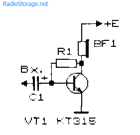
The simplest ULF, made according to the scheme with a common emitter, is shown in Fig. 1. A telephone capsule is used as a load. The permissible supply voltage for this amplifier is 3 ... 12 V.
It is desirable to determine the value of the bias resistor R1 (tens of kΩ) experimentally, since its optimal value depends on the supply voltage of the amplifier, the resistance of the telephone capsule, and the transmission coefficient of a particular transistor instance.
Rice. 1. Scheme of a simple ULF on one transistor + capacitor and resistor.
To select the initial value of the resistor R1, it should be taken into account that its value should be about a hundred or more times higher than the resistance included in the load circuit. To select a bias resistor, it is recommended to sequentially turn on a constant resistor with a resistance of 20 ... 30 kΩ and a variable with a resistance of 100 ... 1000 kΩ, after which, by applying a small amplitude audio signal to the amplifier input, for example, from a tape recorder or player, rotate the variable resistor knob to achieve best quality signal at its highest volume.
The value of the capacitance of the transition capacitor C1 (Fig. 1) can be in the range from 1 to 100 μF: the larger the value of this capacitance, the lower frequencies the ULF can amplify. To master the technique of amplification low frequencies it is recommended to experiment with the selection of element ratings and operating modes of amplifiers (Fig. 1 - 4).
Improved Single Transistor Amplifier Options
Complicated and improved in comparison with the circuit in fig. 1 amplifier circuits are shown in Fig. 2 and 3. In the diagram in fig. 2, the amplification stage additionally contains a chain of frequency-dependent negative feedback(resistor R2 and capacitor C2), which improves the signal quality.

Rice. 2. Scheme of a single-transistor ULF with a frequency-dependent negative feedback circuit.

Rice. 3. A single transistor amplifier with a divider for supplying bias voltage to the base of the transistor.
Rice. 4. Single transistor amplifier with automatic bias setting for the base of the transistor.
In the diagram in fig. 3, the bias to the base of the transistor is set more "rigidly" using a divider, which improves the quality of the amplifier when its operating conditions change. The "automatic" setting of the bias based on the amplifying transistor is used in the circuit in Fig. 4.
Two-stage transistor amplifier
By connecting in series two simplest amplification stages (Fig. 1), you can get a two-stage ULF (Fig. 5). The gain of such an amplifier is equal to the product of the gains of the individual stages. However, it is not easy to obtain a large sustained gain by subsequently increasing the number of stages: the amplifier is likely to self-excite.

Rice. 5. Scheme of a simple two-stage bass amplifier.
New developments of low-frequency amplifiers, whose circuits are often cited in the pages of magazines in recent years, pursue the goal of achieving a minimum total harmonic distortion, increasing output power, expanding the frequency band to be amplified, etc.
At the same time, when setting up various devices and conducting experiments often requires a simple ULF, which can be assembled in a few minutes. Such an amplifier should contain a minimum number of deficient elements and operate over a wide range of supply voltage and load resistance variations.
ULF circuit on field-effect and silicon transistors
The diagram of a simple LF power amplifier with direct connection between the stages is shown in Fig. 6 [Rl 3 / 00-14]. The input impedance of the amplifier is determined by the value of the potentiometer R1 and can vary from hundreds of ohms to tens of megohms. The output of the amplifier can be connected to a load with impedance from 2 ... 4 to 64 Ohm and higher.
With a high-resistance load, the KT315 transistor can be used as VT2. The amplifier is operational in the range of supply voltages from 3 to 15 V, although its acceptable operability remains even when the supply voltage is reduced to 0.6 V.
The capacitance of the C1 capacitor can be selected in the range from 1 to 100 μF. In the latter case (C1 = 100 μF), the ULF can operate in the frequency range from 50 Hz to 200 kHz and above.

Rice. 6. Scheme simple amplifier low frequency on two transistors.
The amplitude of the ULF input signal should not exceed 0.5 ... 0.7 V. The output power of the amplifier can vary from tens of mW to units of W, depending on the load resistance and the magnitude of the supply voltage.
Tuning the amplifier consists in the selection of resistors R2 and R3. With their help, the voltage at the drain of the transistor VT1 is set, equal to 50 ... 60% of the voltage of the power source. Transistor VT2 must be installed on a heat sink plate (heat sink).
Direct-coupled tracked ULF
In fig. 7 shows a diagram of another seemingly simple ULF with direct connections between the stages. This kind of connection improves frequency characteristics amplifier in the low-frequency region, the circuit as a whole is simplified.

Rice. 7. Schematic diagram three-stage ULF with direct connection between the stages.
At the same time, amplifier tuning is complicated by the fact that each amplifier impedance has to be selected individually. Roughly the ratio of resistors R2 and R3, R3 and R4, R4 and R BF should be within (30 ... 50) to 1. Resistor R1 should be 0.1 ... 2 kOhm. Calculation of the amplifier shown in Fig. 7 can be found in the literature, for example [P 9 / 70-60].
Cascade ULF circuits on bipolar transistors
In fig. 8 and 9 show diagrams of cascode ULF bipolar transistors. Such amplifiers have a fairly high gain Ku. The amplifier in Fig. 8 has Ku = 5 in the frequency band from 30 Hz to 120 kHz [MK 2 / 86-15]. ULF according to the scheme in Fig. 9 with a harmonic coefficient of less than 1% has a gain of 100 [RL 3 / 99-10].
![]()
Rice. 8. Cascade ULF on two transistors with gain = 5.

Rice. 9. Cascade ULF on two transistors with gain = 100.
Economical ULF on three transistors
For portable electronic equipment, an important parameter is the efficiency of the ULF. The diagram of such an ULF is shown in Fig. 10 [RL 3 / 00-14]. Here, a cascade connection of a field-effect transistor VT1 and a bipolar transistor VT3 is used, and the transistor VT2 is turned on in such a way that it stabilizes the operating point VT1 and VT3.
With an increase in the input voltage, this transistor shunts the emitter-base transition VT3 and reduces the value of the current flowing through the transistors VT1 and VT3.

Rice. 10. Scheme of a simple economical bass amplifier on three transistors.
As in the above circuit (see Fig. 6), the input impedance of this ULF can be set in the range from tens of Ohms to tens of MΩ. A telephone capsule was used as a load, for example, TK-67 or TM-2V. The phone capsule, which is connected with a plug, can simultaneously serve as a power switch for the circuit.
The supply voltage of the ULF is from 1.5 to 15 V, although the device remains operational even when the supply voltage drops to 0.6 V. In the supply voltage range of 2 ... 15 V, the current consumed by the amplifier is described by the expression:
1 (μA) = 52 + 13 * (Upit) * (Upit),
where Usup is the supply voltage in Volts (V).
If you turn off the transistor VT2, the current consumed by the device increases by an order of magnitude.
Two-stage ULF with direct connection between stages
Examples of ULF with direct connections and a minimum selection of the operating mode are the circuits shown in Fig. 11 - 14. They have high gain and good stability.

Rice. 11. Simple two-stage ULF for a microphone (low noise, high KU).

Rice. 12. Two-stage amplifier of low frequency on transistors KT315.

Rice. 13. Two-stage low-frequency amplifier on KT315 transistors - option 2.
The microphone amplifier (Fig. 11) is characterized by a low level of intrinsic noise and a high gain [MK 5/83-XIV]. An electrodynamic type microphone is used as a VM1 microphone.
A telephone capsule can also act as a microphone. Stabilization of the operating point (initial bias based on the input transistor) of the amplifiers in Fig. 11 - 13 is carried out due to the voltage drop across the emitter resistance of the second amplification stage.

Rice. 14. Two-stage ULF with a field-effect transistor.
The amplifier (Fig. 14), which has a high input impedance (about 1 MΩ), is made on a field-effect transistor VT1 (source follower) and a bipolar one - VT2 (with a common one).
A cascade low-frequency field-effect transistor amplifier, also having a high input impedance, is shown in Fig. 15.

Rice. 15. circuit of a simple two-stage ULF on two field-effect transistors.
ULF circuits for working with low-ohm load
Typical ULFs designed to operate on a low-impedance load and having an output power of tens of mW and above are shown in Fig. 16, 17.

Rice. 16. Simple ULF for operation with low impedance load switching.
The VA1 electrodynamic head can be connected to the amplifier output, as shown in Fig. 16, or in the diagonal of the bridge (Fig. 17). If the power source is made of two series-connected batteries (accumulators), the right output of the BA1 head according to the scheme can be connected directly to their midpoint, without capacitors СЗ, С4.

Rice. 17. Low-frequency amplifier circuit with the inclusion of a low-impedance load in the diagonal of the bridge.
If you need a circuit of a simple tube ULF, then such an amplifier can be assembled even on one lamp, look at our electronics website in the appropriate section.
Literature: Shustov M.A. Practical Circuitry (Book 1), 2003.
Corrections in the publication: in fig. 16 and 17, instead of diode D9, a chain of diodes is installed.
After mastering the basics of electronics, a novice radio amateur is ready to solder his first electronic designs. Audio power amplifiers are generally the most repeatable designs. There are a lot of schemes, each one differs in its parameters and design. This article will consider several of the simplest and completely working amplifier circuits that can be successfully repeated by any radio amateur. The article does not use complex terms and calculations, everything is simplified as much as possible so that no additional questions arise.
Let's start with a more powerful circuit.
So, the first circuit is made on the well-known TDA2003 microcircuit. This is a mono amplifier with up to 7 watts of output power into a 4 ohm load. I want to say that the standard circuit for switching on this microcircuit contains a small number of components, but a couple of years ago I came up with another circuit on this microcircuit. In this circuit, the number of component parts is minimized, but the amplifier has not lost its sound parameters... After the development of this circuit, I began to make all my amplifiers for low-power speakers on this circuit.
The circuit of the presented amplifier has a wide range of reproducible frequencies, the supply voltage range is from 4.5 to 18 volts (typical 12-14 volts). The microcircuit is installed on a small heat sink, since the maximum power reaches up to 10 watts.
The microcircuit is capable of operating on a load of 2 ohms, which means that 2 heads with a resistance of 4 ohms can be connected to the amplifier output.
The input capacitor can be replaced with any other capacitor with a capacity from 0.01 to 4.7 μF (preferably from 0.1 to 0.47 μF), both film and ceramic capacitors... It is advisable not to replace all other components.

Volume control from 10 to 47 kOhm.
The output power of the microcircuit allows it to be used in low-power PC speakers. It is very convenient to use a microcircuit for stand-alone speakers to mobile phone etc.
The amplifier works immediately after switching on, it does not need additional adjustment. It is recommended to additionally connect the minus power supply to the heatsink. All electrolytic capacitors are preferably 25 volts.
The second circuit is assembled on low-power transistors, and is more suitable as a headphone amplifier.

This is probably the highest quality circuit of its kind, the sound is clear, all frequency spectrum... WITH good headphones, it feels like you have a full-fledged subwoofer.

The amplifier is assembled on only 3 reverse conduction transistors, as the cheapest option, transistors of the KT315 series were used, but their choice is wide enough.
The amplifier can operate on a low-impedance load, up to 4 ohms, which makes it possible to use the circuit to amplify the signal of a player, radio receiver, etc. A 9-volt krone-type battery is used as a power source.
In the final stage, KT315 transistors are also used. To increase the output power, you can use KT815 transistors, but then you will have to increase the supply voltage to 12 volts. In this case, the power of the amplifier will reach up to 1 Watt. The output capacitor can have a capacitance from 220 to 2200 μF.
The transistors in this circuit do not heat up, therefore no cooling is needed. When using more powerful output transistors, you may need small heatsinks for each transistor.
And finally, the third scheme. An equally simple, but proven version of the amplifier structure is presented. The amplifier is capable of operating from undervoltage up to 5 volts, in this case output power The PA will be no more than 0.5 W, and the maximum power when powered by 12 volts reaches up to 2 watts.

The output stage of the amplifier is built on a domestic complementary pair. Adjust the amplifier by selecting the resistor R2. For this, it is advisable to use a 1kOhm trimmer. Slowly rotate the regulator until the quiescent current of the output stage is 2-5 mA.
The amplifier does not have a high input sensitivity, so it is advisable to use a preamplifier before the input.

A diode plays an important role in the circuit; it is here to stabilize the mode of the output stage.
The transistors of the output stage can be replaced with any complementary pair of the corresponding parameters, for example, KT816 / 817. The amplifier can drive low-power stand-alone speakers with a load impedance of 6-8 ohms.
List of radioelements
| Designation | Type of | Denomination | Quantity | Note | Shop | My notebook | |
|---|---|---|---|---|---|---|---|
| Amplifier on the TDA2003 chip | |||||||
| Audio amplifier | TDA2003 | 1 | Search in Chip and Dip | Into notepad | |||
| C1 | 47 uF x 25V | 1 | Search in Chip and Dip | Into notepad | |||
| C2 | Capacitor | 100 nF | 1 | Film | Search in Chip and Dip | Into notepad | |
| C3 | Electrolytic capacitor | 1 μF x 25V | 1 | Search in Chip and Dip | Into notepad | ||
| C5 | Electrolytic capacitor | 470 uF x 16V | 1 | Search in Chip and Dip | Into notepad | ||
| R1 | Resistor | 100 ohm | 1 | Search in Chip and Dip | Into notepad | ||
| R2 | Variable resistor | 50 kΩ | 1 | 10 kΩ to 50 kΩ | Search in Chip and Dip | Into notepad | |
| Ls1 | Dynamic head | 2-4 Ohm | 1 | Search in Chip and Dip | Into notepad | ||
| Amplifier on transistors circuit number 2 | |||||||
| VT1-VT3 | Bipolar transistor | KT315A | 3 | Search in Chip and Dip | Into notepad | ||
| C1 | Electrolytic capacitor | 1 uF x 16V | 1 | Search in Chip and Dip | Into notepad | ||
| C2, C3 | Electrolytic capacitor | 1000 uF x 16V | 2 | Search in Chip and Dip | Into notepad | ||
| R1, R2 | Resistor | 100 kΩ | 2 | Search in Chip and Dip | Into notepad | ||
| R3 | Resistor | 47 k Ohm | 1 | Search in Chip and Dip | Into notepad | ||
| R4 | Resistor | 1 kΩ | 1 | Search in Chip and Dip | Into notepad | ||
| R5 | Variable resistor | 50 kΩ | 1 | ||||
Transistor amplifier practical example of work
In the amplification mode, the transistor amplifier works in receiver circuits and audio frequency amplifiers (UZCH and ULF). During operation, small currents are used in the base circuit that control large currents in the collector. This is the difference between the amplification mode and the switching mode, which only opens or closes the transistor depending on Ub at the base.
As an experience for a novice radio amateur, we will assemble the simplest amplifier transistor, in accordance with the proposed circuit and figure.

To the collector VT1 connect a high impedance phone BF2, between the base and the minus of the power supply, we connect the resistance Rb, and the decoupling capacitance of the capacitor C sv.
Of course a strong gain sound signal we will not get from such a scheme, but we can hear the sound in the phone BF1 all the same, you can, because we have assembled your first amplifier stage.
An amplifier stage is a transistor circuit with resistors, capacitors and other radio components that provide the last condition works as a transistor amplifier. In addition, let's say right away that the amplifying stages can be interconnected and multi-stage amplifying devices can be obtained.
When the power source is connected to the circuit, a small negative voltage of the order of 0.1 - 0.2 V, called the bias voltage, goes to the base of the transistor through the resistance Rb. It slightly opens the transistor, that is, it lowers the height of potential barriers, and a small current begins to flow through the junctions of the semiconductor device, which keeps the amplifier in standby mode, from which it can instantly exit as soon as an input signal appears at the input.

Without the presence of a bias voltage, the emitter junction will be locked and, like a diode, will not pass the positive half-cycles of the input voltage, and amplified signal will be distorted.
If you connect another telephone to the amplifier input and use it as a microphone, then it will convert the sound vibrations arising on its membrane into an alternating voltage of the audio range, which will follow through the capacitance Csv to the base of the transistor.
The CCB capacitor is the connecting component between the phone and the base. It perfectly passes the AF voltage, but creates a serious obstacle to the direct current going from the base circuit to the phone. In addition, the phone has an internal resistance of the order of 1600 Ohm, therefore, without this capacitance of the capacitor, the base through the internal resistance would be connected to the emitter and there would be no amplification.
Now, if you start talking into the phone-microphone, then the emitter circuit will cause fluctuations in the current of the phone ITLF, which will control high current arising in the collector and these amplified vibrations, converted by the second telephone into ordinary sound, we will hear.

The signal amplification process can be represented as follows. At the moment when the input signal voltage Uin is absent, insignificant currents flow in the base and collector circuits (straight sections of the diagram a, b, c), set by the applied voltage of the power supply, the bias voltage and the amplifying characteristics of the bipolar transistor.
As soon as the input signal arrives at the base (the right side of diagram a), then, depending on it, the currents in the circuits of the three-output semiconductor device will begin to change (the right part of the diagram b, c).

In the negative half-wave of the signal, when Uin and the power supply voltage are summed at the base, the currents flowing through the transistor increase.
With a positive wave, the negative voltage at the base decreases, as do the flowing currents. This is how the transistor amplifier works.
If you connect not a telephone but a resistor to the output, then the voltage of the variable component of the amplified signal that appears on it can be brought to the input circuit of the second stage for additional amplification. One device is capable of amplifying the signal by 30-50 times.

VTs of the opposite n-p-n structures... But for them, the polarity of the power supply must be reversed.
For the amplifier transistor to work, a constant bias voltage must be supplied to its base, relative to the emitter, along with the input signal voltage, which opens the semiconductor device.
For germanium VT, the opening voltage should be no more than 0.2 volts, and for silicon 0.7 volts. Only when the emitter junction of the transistor is used to detect the signal is not bias voltage applied to the base, but we will talk about this later.
A low frequency amplifier (ULF) is an integral part of most radio engineering devices such as a TV, player, radio and various household appliances. Consider two simple schemes two-stage ULF on.
The first version of ULF on transistors
In the first version, the amplifier is built on silicon transistors n-p-n conductivity. Input signal comes through the variable resistor R1, which in turn is the load resistance for the signal source circuit. connected to the collector circuit of the transistor VT2 of the amplifier.
Tuning the amplifier of the first option is reduced to the selection of resistances R2 and R4. The value of the resistances must be chosen so that the milliammeter connected to the collector circuit of each transistor shows a current in the region of 0.5 ... 0.8 mA. According to the second scheme, it is also necessary to set the collector current of the second transistor by selecting the resistance of the resistor R3.
In the first option, it is possible to use transistors of the KT312 brand, or their foreign counterparts, however, it will be necessary to set the correct voltage bias of the transistors by selecting the resistances R2, R4. In the second variant, in turn, it is possible to use KT209, KT361 silicon transistors, or foreign analogues. In this case, you can set the operating modes of the transistors by changing the resistance R3.
Instead of headphones, it is possible to connect a speaker with high resistance... If you need to get more powerful sound amplification, then you can assemble an amplifier for that provides amplification up to 15 watts.
The power supply must provide a stable or unstable bipolar supply voltage of ± 45V and a current of 5A. This ULF transistor circuit is very simple, since a pair of powerful complementary Darlington transistors is used in the output stage. In accordance with the reference characteristics, these transistors can switch current up to 5A at an emitter-collector junction voltage of up to 100V.
The ULF circuit is shown in the figure below.
The signal requiring amplification through the preliminary ULF is fed to the preliminary differential amplifier stage built on composite transistors VT1 and VT2. The use of a differential circuit in the amplifier stage reduces noise effects and provides negative feedback. The OS voltage is supplied to the base of the transistor VT2 from the output of the power amplifier. DC feedback is realized through the resistor R6. The OS for the variable component is carried out through the resistor R6, but its value depends on the ratings of the R7-C3 chain. But it should be borne in mind that too much increase in resistance R7 leads to excitation.

The DC operation mode is provided by the selection of the resistor R6. The output stage on Darlington transistors VT3 and VT4 operates in class AB. Diodes VD1 and VD2 are needed to stabilize the operating point of the output stage.
The VT5 transistor is designed to drive the output stage, the signal from the differential output is fed to its base. pre-amplifier, as well as a constant bias voltage, which determines the mode of operation of the output stage in direct current.
All capacitors in the circuit must be rated for a maximum constant voltage of at least 100V. It is recommended to fix the transistors of the output stage on radiators with an area of at least 200 cm squared
The above circuit of a simple two-stage amplifier is designed to work with headphones or for use in simple devices with pre-amplifier function.
The first transistor of the amplifier is connected with a common emitter, and the second transistor with a common collector. The first stage is designed for basic voltage signal amplification, and the second stage amplifies the power already.

The low output impedance of the second stage of a two-stage amplifier, called an emitter follower, allows you to connect not only headphones with high impedance, but also other types of acoustic signal transducers.
This is also a two-stage ULF circuit made on two transistors, but already of opposite conductivity. Its main feature is that the connection between the cascades is direct. Covered by the OOS through the resistance R3, the bias voltage from the second stage passes to the base of the first transistor.

Capacitor SZ, shunts resistor R4, reduces AC feedback, thereby reducing the gain VT2. By selecting the value of the resistor R3, the operating mode of the transistors is set.
UMZCH on two transistors |

This fairly lightweight audio power amplifier (UMZCH) can be soldered on just two transistors. With a supply voltage of 42VDC, the amplifier's output power reaches 0.25W into a 4 ohm load. The current consumption is only 23 mA. The amplifier operates in single-ended mode "A".
The low frequency voltage from the signal source goes to the volume control R1. Further, through the protective resistor R3 and the capacitor C1, the signal turns out to be based on the bipolar transistor VT1 connected according to the scheme with a common emitter. The amplified signal through R8 is fed to the gate of a powerful field-effect transistor VT2 connected according to a circuit with a common source and its load is the primary winding of a step-down transformer. A dynamic head or a speaker system can be connected to the secondary winding of the transformer.
In both transistor stages, there is a local negative feedback for direct and alternating current, as well as a common OOS circuit.
In the case of an increase in the voltage at the gate of the field-effect transistor, the drain resistance of the source of its channel decreases and the voltage at its drain decreases. This also affects the level of the signal going to the bipolar transistor, which reduces the gate-source voltage.
Together with local negative feedback circuits, thus, the modes of operation of both transistors are stabilized even in the case of a slight change in the supply voltage. The gain depends on the ratio of the resistances of the resistors R10 and R7. Zener diode VD1 is designed to prevent the failure of the field-effect transistor. The power supply of the amplifier stage at VT1 is made through the RC filter R12C4. Capacitor C5 blocking on the power supply circuit.
The amplifier can be assembled on printed circuit board dimensions 80 × 50 mm, all elements are located on it except for the step-down transformer and the dynamic head

Adjustment of the amplifier circuit is carried out at the supply voltage at which it will operate. For fine tuning it is recommended to use an oscilloscope, the probe of which is connected to the drain pin of the field-effect transistor. Having fed a sinusoidal signal with a frequency of 100 ... 4000 Hz to the amplifier input, by adjusting the trimmer R5, they ensure that there are no noticeable sinusoidal distortions with the largest possible signal amplitude swing at the drain terminal of the transistor.
The output power of the field-effect transistor amplifier is small, only 0.25W, the supply voltage is from 42V to 60V. The impedance of the dynamic head is 4 Ohm.
The audio signal through the variable resistance R1, then R3 and the blocking capacitance C1 goes to the amplifier stage on a bipolar transistor according to the common emitter circuit. Further, from this transistor, the amplified signal passes through the resistance R10 to the field-effect transistor.

The primary winding of the transformer is a load for the field-effect transistor, and a four-ohm dynamic head is connected to the secondary winding. By the ratio of the resistances R10 and R7, we set the degree of voltage amplification. In order to protect the unipolar transistor, a Zener diode VD1 is added to the circuit.
All component ratings are shown in the diagram. The transformer can be used like TVK110LM or TVK110L2, from an old TV frame scanner or similar.
UMZCH according to Ageev's scheme |
I came across this circuit in an old issue of the radio magazine, the impressions from it remained the most pleasant, firstly, the circuit is so simple that a novice radio amateur can also assemble it, and secondly, provided that there are working components and proper assembly, it does not require adjustment.

If you are interested in this circuit, then the rest of the details on its assembly you can find in the radio magazine # 8 for 1982.
High quality transistor ULF |