When designing audio-frequency tube amplifiers (UMZCH), many authors use output stages operating in class A. They argue their decision with the minimum coefficient of nonlinear distortion of such stages. However, the stages operating in class A have a fairly decent initial anode current (the operating point lies in the middle of the linear section of the lamp characteristic). Consequently, the efficiency of the lamp will be very low. A constant current flowing through the lamp will heat its electrodes. If you do not provide for forced cooling of the lamps, then their electrodes will be intensively destroyed. It should be noted that when building class A amplifiers with an output power of 10 ... 20 W, it is still possible to create a compact cooling system. But if the amplifier is to be counted on, for example, for 100 W, then a rather bulky "cooler" will have to be built.
Therefore, it is more profitable to use a more economical mode of operation of lamps in class B. The disadvantage of this mode is the increased level of nonlinear distortions. This is due to the fact that in this mode the operating point of the lamp lies in a more nonlinear initial section of the lamp characteristic. With a push-pull circuit for switching on lamps, this causes distortion in the form of a "step". There is a very simple way to compensate for such distortions. For this, the amplifier must be covered with deep negative feedback.
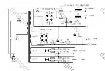
The proposed amplifier is powered by a two-transformer power supply (Fig. 1). The TZ transformer provides power to the anode circuits of the entire circuit and the grid circuits of the amplifier's output lamps, T4 generates incandescent voltages, bias voltages on the grids of the output lamps and voltage to power the fans that cool the amplifier. To reduce the background level, the pre-amplifier lamps are heated from a direct current source.

Rice. 1. Two-transformer power supply
Schematic diagram amplifier is shown in Fig. 2. A preamplifier is assembled on a small-sized double triode VL1. The input signal levels are regulated by variable resistors R1 and R2. Left and right channel signals are routed to the 3-band tone controls. Further, the signals through the compensating amplifier on the double triode VL2 are fed to the phase inverters on the double triode VL3. Correcting RC circuits connected to the cathodes of VL2 triodes reduce the harmonic distortion of the amplifier and prevent it from self-excitation at infra-low frequencies. The VL3 anodes produce antiphase signals necessary for the operation of push-pull output stages. The antiphase signals are "swept" by the preamplifiers on the double triodes VL4, VL5 to the levels required to excite the output tubes VL6 ... VL9. Both tetrodes in each lamp are connected in parallel to increase the output power. The lamps are loaded with output transformers T1, T2.
Rice. 2. Schematic diagram of the amplifier (click to enlarge)
Transformers agree high resistance lamps with speaker impedance.
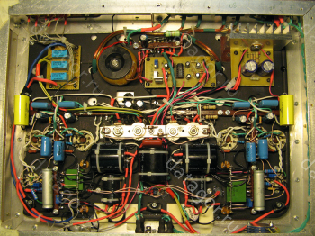
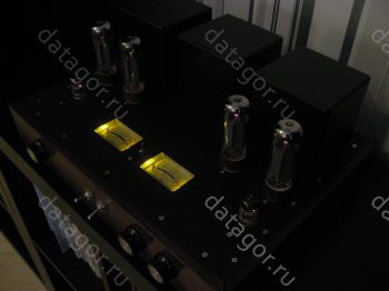
The amplifier is assembled in a duralumin case. Fans M1 and M2 are positioned so that they blow over the output lamps. XS1 - jack "JACK" or "miniJACK". R1, R2, R11, R13, R15, R17, R19, R21 - any variable resistors of a suitable type. SA1 must withstand a current of up to 6 A at a supply voltage of 220 V. For T1 and T2, W-shaped cores with a section of 32x64 mm are used. Windings I, III each contain 600 turns of PEVTL-2 wire d0.4 mm, and windings IIa and IIb each contain 100 turns of the same wire. Winding IV contains 70 turns of wire PEV-2 d1.2 mm. TZ and T4 are wound on toroidal cores with a section of 65x25 mm (T3) and 40x25 mm (T4). T3 has a primary winding, consisting of 600 turns of PEVTL-2 wire d0.8 mm, and a secondary one, consisting of two windings of 570 turns of the same wire. The primary winding T4 consists of 1600 turns of PEVTL-2 wire d0.31 mm, winding II - 500 turns of the same wire, III and IV - 52 and 104 turns of PEVTL-2 wire d0.8 mm. The order of winding windings for T1 and T2 is shown in Fig. 3.

Rice. 3. The order of winding windings for T1 and T2
Setting up an amplifier begins with a power source. Remove the VL6 ... VL9 lamps from the sockets and turn on the power. In this case, HL1 should light up, and M1 and M2 should work. DC output voltages are measured, which should differ from those indicated according to the scheme by no more than ± 10%. The volume control slides are set to the extreme right, and the tone controls are set to the middle position. Temporarily disconnect the OOS circuits (R52, C46, C47, R75, C38, C51). Sinusoidal signals with a frequency of 1 kHz and an amplitude of 250 mV are fed to the inputs of the LC and PC. With a two-channel oscilloscope, antiphase signals at the anodes of the VL4, VL5 lamps are monitored (their amplitudes should be the same, and the shape should not be distorted). VL6 ... VL9 is installed in place, and either acoustic systems or (better) load equivalents (resistors 8 Ohm x 150 W) are connected to the outputs. An undistorted signal should also be observed at the output. The OOS chains are restored. If the amplifier is self-excited, you should select capacities C38, C47 or resistors R52, R75. In this case, it is impossible to greatly reduce the OOS, since the coefficient of nonlinear distortion will increase accordingly. This completes the amplifier setup.
In order to properly operate the amplifier, it should be remembered that turning on the amplifier without load is strictly prohibited. Failure to comply with this requirement will lead to failure of the output lamps and transformers.
See other articles section.
I used to be prejudiced about the sound of push-pull tube amplifiers, believing that a single-cycle would give them "a hundred points ahead."
Why? I once had a two-stroke tube amplifier, assembled “according to the scheme I don’t know”, on EL34 lamps. It did not sound.
But then I hadn't assembled amplifiers yet. And I decided to close this issue for myself by collecting PP on EL34. Moreover, I had a pair of output transformers in my store, donated by one very good person! These are:
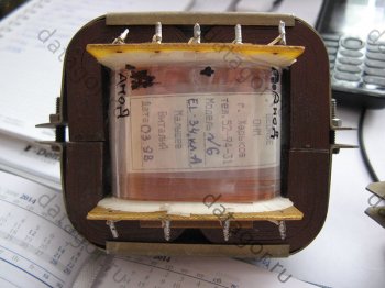
Amplifier circuit
I chose the scheme "according to Manakov":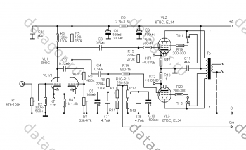
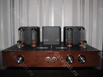
Began, as always, with the assembly of the case. I will not dwell in detail on the technology of its manufacture, I talked about this in detail in As always, I assembled the amplifier on a separate metal chassis, mounted on racks inside the case. This minimizes the number of holes in the top cover of the amplifier. For the manufacture of the case, I used an aluminum corner 20x20x2.0, duralumin sheets, 1.5 mm thick (for the top cover) and 1 mm (for the bottom cover and chassis). The paneling is made of beech wood stained and varnished in several layers. The dural is spray-painted. This time I used ready-made caps for transformers, having ordered them in advance.
All mechanical work was done on the balcony. Used a folding workbench, drill, electric jigsaw, disk grinder manual milling cutter, dremel and professional miter box. Over the years of radio amateurism, I have grown solidly good tools... This allows me to fulfill many complex work much faster and more accurate. But most of this work can be done manually. With more effort and time, of course.
Radio components, in general, are the most common. I used capacitors K78-2 and K71-7 as dividing capacitors, everything else was a “hodgepodge”.
I bought EL34 lamps already matched into the "four".

Power transformer: torus, 270Vx0.6A - anode secondary, 50Vx0.1A - secondary for displacement, 2 × 6.3 × 4A - for powering the heaters.
I made some changes to the diagram
Instead of a 6H9C lamp, I first arrogantly tried to use 6H2P (EB). As a result, I got ... "dead" sound. Not that! Not at all. And the holes for the panels are drilled, and the chassis is already installed. What to do? I started looking for a replacement for this lamp. It turned out that the ECC85 lamp (according to the reviews of colleagues on the forums) is "very even". I got a pair. Changed the values of the "strapping" resistors. The anodes have 36 kOhm (2W), cathode resistors - 180 Ohm, the bias is about 1.5 V. I must say right away that this was very good for the sound!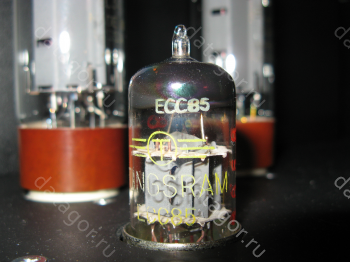
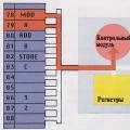
Electronic choke
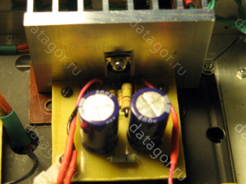
Instead of conventional chokes, I also used an "electronic choke" assembled according to this scheme:
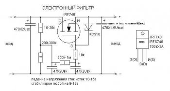
Note that the real voltage drop across the choke is about 20-25 V. Take this into account in your design!
Throttle PCB is also included.
Input selector
Organized an input selector for three TAKAMISAWA relays (by the number of inputs), which commutate a low-current signal. I did not make a printed circuit board for the switch, I collected everything on a breadboard.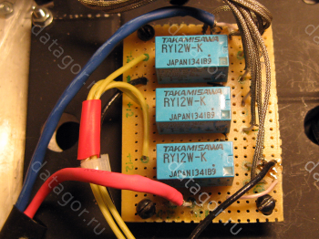
The scheme is something like this:
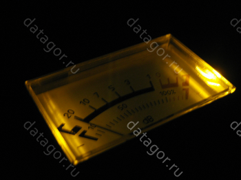
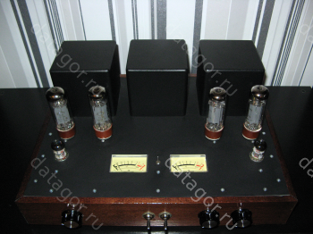
For the sake of beauty, I put dial indicators. The indicators are controlled by the domestic K157DA1 microcircuit. The circuit has been converted to a single-supply supply, a printed circuit board is included.
The switch, the K157DA1 microcircuit and the indicator backlight diodes are powered from one stabilized voltage source.
From the assembly features
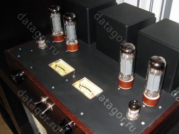
The most important is the layout of the land. It is clearly seen that I organized two ground points, collected the grounds of the left and right channels on them and connected them to the "minus" of the anode voltage filter capacitor. As a result, together with the "electronic choke", it gave a very good effect. I can't hear the background at all. Neither 10, nor 5, nor 2 centimeters from the speaker.
Amplifier setup
Here I am quoting Manakov in full:The first stage is adjusted by a constant voltage drop of 1.8-2 V at the control point on the cathode resistor by selecting the value of this resistor.
The second stage is adjusted for the DC voltage drop in control points on cathode resistors 1 Ohm of the output stage lamps, by adjusting the bias voltage on the control grids of these lamps. The voltage drop across them should be 0.035-0.04 V, which corresponds to the anode current of each lamp 35-40 mA. The most "economical" ones can reduce the currents of the output lamps to 25-30 mA. I think it is unnecessary to remind that all these settings must be made in the silent mode.
According to the alternating voltage, the phase-inverted stage is adjusted by supplying an alternating voltage of about 0.5 V with a frequency of 3 kHz to the grid of the left triode of the 6N9C lamp, a trimming resistor in the grid circuit of the right triode of the lamp sets the same alternating voltage at the anodes of the lamp. In this case, you need to use a voltmeter with an input resistance of at least 1 megohm.
I will only add that when using EL34 lamps, the quiescent currents can (and should!) Be boldly raised to about 56 - 60 mA, with an anode voltage of about 350 V.
Files
Blueprints printed circuit boards e-mail choke and level gauge:▼
I'll make a reservation right away - this anthology in no way pretends to be a manual for tube circuitry. Schemes (including historical ones) were selected according to a combination of technical solutions, if possible with `` zest ''. And everyone has different tastes, so don’t excuse me if you don’t guess right ... In the old schemes, a number of denominations are reduced to standard ones.
To increase the output power of the amplifiers, in addition to the `` parallelization '' of the lamps, push-pull cascades were used back in the 30s. (push-pull) ... To excite a push-pull stage, two antiphase voltages are required, which are most easily obtained using a transformer. This is still done in the most uncompromising designs, but the degree of influence of the inter-tube transformer on the quality of the signal is almost greater than that of the output. Therefore, in the overwhelming majority of push-pull amplifiers, a special phase-inverted stage is used to obtain antiphase voltages.
- The main types of phase-inverted cascades
- separate inverting stage in one of the amplifier arms
- autobalanced bass reflex
- cathodic coupled phase inverter
- split-load bass reflex
Each of the solutions has advantages and disadvantages. During the heyday of high-quality tube amplifiers, phase inverters with split load and cathodic coupling were most widely used.
A cathodic coupled phase inverter gives some gain, but the identity of the output signals depends on the degree of coupling. A deep connection can be obtained only when using a large connection resistance (for this, the scheme was called long tail - "long-tailed") or current sources in the cathode circuit (and this was not at all welcome then). In addition, the output resistances of the arms of such a phase inverter differ significantly (one triode is connected according to the scheme with a common cathode, the second with a common grid).
A split-load phase inverter produces identical signals, but attenuates them somewhat. Therefore, you have to increase the gain to the phase inverter (which is fraught with its overload) or use a push-pull pre-final stage. However, it is this type of phase inverter that is most widely used in industrial designs, since it provides good repeatability during serial production.
The issue of saving in those years was of the highest priority. Both radio amateurs and designers were very confused by an extra lamp. Therefore, it is not surprising that at the beginning of the 50s, schemes of push-pull amplifiers appeared on the pages of radio engineering publications that did not contain a separate phase inverter. The output stage of such amplifiers was made according to a cathodic coupled circuit and worked in a `` clean '' class A. Both new circuits and alteration of existing ones were proposed. single-ended amplifiers into two-stroke. On our side of the Iron Curtain, this type of amplifiers did not take root due to their low efficiency, but on the other side they were in use for a long time.
Extremely simple circuit of such an amplifier, intended for repetition by amateurs, is given below (thanks to Klaus who sent the circuit - without it the picture was incomplete). Pay attention to the date ...
fig. 1. Simple push-pull amplifier Pout = 6 W. The output stage is made according to the scheme with cathodic coupling. The reduced load resistance is 8 kOhm. The design data of the transformer is unknown. The power supply uses a full-wave rectifier on a 5Y3GT direct-heated kenotron and an LC filter. / Melvin Leibovitz Hi-Fi Power Amplifier (Electronic World, June 1961)
It is interesting to include a volume control at the input of the final stage and only one transition capacitor. The degree of cathodic coupling is low, so the character of the sound is likely to be like that of a single-cycle (with even harmonics). There is no general OOS, since the gain margin is small.
However, the introduction of OOS in a pentode amplifier is highly desirable - without it, the output impedance is very high. This is good only for the midrange band (because it reduces intermodulation distortion in the dynamics), but is contraindicated for all other applications. Deep feedback can be introduced into the amplifier only with direct connection of the stages.
fig. 2. Push-pull amplifier class A. The amplifier is made according to the scheme with direct coupling of the stages and is covered by deep OOS (~ 30 dB). The push-pull output stage operates in class A. It is made according to the scheme with cathodic coupling and does not require a separate phase-inverted stage. The VL3 grid is AC grounded. Part of the voltage from the cathodes of the output tubes is applied to the VL1 screening grid, which stabilizes the DC mode.
The adjustment is reduced to the selection of R1 ... R3 so that the voltage on the control grids of the lamps is -12 V relative to their cathodes.
The output transformer is made on the Ш-22х50 core. The primary winding contains 2x1000 turns of wire d = 0.18 mm, the secondary - 42 turns of wire d = 1.25. The windings are sectioned, the secondary winding is placed between the layers of the primary. (V. Pavlov. High-quality bass amplifier (Radio, No. 10/1956, p.44)
Amplifiers in A mode provide high quality sound, but switching to AB mode with the same plate dissipation results in two to three times the power output. The output stage in AB mode can no longer work with cathodic coupling, therefore, a separate phase-inverted stage cannot be dispensed with.
The desire to reduce, if not the number of tubes, then at least the number of cylinders, led to the emergence of an amplifier circuit based on two triode-pentodes. Low-frequency triode-pentodes were at one time specially designed for single-ended amplifiers of receivers and televisions (the triode part was used in the driver, the pentode part in the output stage). However, in a two-stroke application, they also did not disappoint. The scheme published below has had many incarnations. The ultra-linear version, for example, was in the very first edition of Gendin's book High Quality Amateur ULFs (1968)
Fig. 3 Two-pull amplifier on triode-pentodes. Pout = 10 W. The phase inverter is based on a shared load scheme, the connection with the first stage is direct. The output stage is pentode with a fixed offset. There are also known variants of this circuit with ultra-linear switching of the output lamps, with combined and automatic bias. The design data of the transformer is unknown. The R3C2 circuit ensures the stability of the closed-loop amplifier.
By the way, about the ultra-linear switching of the output pentodes. In the push-pull version, they have one more advantage - additional compensation of harmonics arising in the output stage. Therefore, the overwhelming majority of amateur designs are made exactly according to the ultra-linear version. In industrial designs of domestic manufacture, ultralinear amplifiers, again, did not take root due to the complexity of the output transformer. To obtain high characteristics, complete symmetry of the structure, sectioning of the windings, and complex switching are required. When using mass-produced transformers, the benefits of using an ultra-linear circuit are not noticeable.
The following diagram has become a classic and has served as the basis for countless designs.
fig. 4. Ultralinear amplifier Pout = 12 W, Kg< 0,5% Выходной трансформатор выполнен на сердечнике Ш 19х30 мм. Первичная обмотка содержит 2х(860+1140) витков проводом d=1,3 мм. Схема практически не нуждается в налаживании, что снискало ей популярность в промышленных и любительских конструкциях. Фазоинвертор выполнен по схеме с разделенной нагрузкой. В. Лабутин - Ультралинейный усилитель (Радио, №11/1958, с.42-44)
Despite the high performance, both conventional pentode and ultra-linear amplifiers have rarely been used without general feedback. The use of OOS reduces the output impedance of the amplifier and improves the working conditions of the low-frequency heads. But to reduce the output impedance of the amplifier, you can use not only negative, but also positive feedback. The next amplifier uses combined feedback.
fig. 5. Ultra-linear amplifier The main feature of the amplifier is a combination of voltage feedback and current feedback, which improves the matching of the amplifier with the dynamic head in the main mechanical resonance region. The depth of both feedbacks controlled synchronously, which excludes self-excitation of the amplifier.
The first stage is a voltage amplifier. The phase inverter is made according to the scheme with cathodic coupling. The output stage is made according to a typical ultra-linear circuit and is supplemented by a balancing regulator RP1. On the second triode VL1 is made microphone amplifier The output transformer is made on the core Ш25х40 The primary winding contains 2x (1100 + 400) turns of wire d = 0 18mm, the secondary - 82 turns of wire d = 0.86mm (60m) V. Ivanov - LF amplifier (Radio No. 11/1959 p.47 -49)
The triode output stage has low distortion and low output impedance even without general feedback. The characteristics of the cascade are weakly dependent on the reduced load resistance. This allows the inductance of the output transformer to be reduced. The following are two options for an amplifier circuit with a dual triode output stage.
fig. 6. Triode amplifier Pout = 2.5W (+ 250V) Pout = 3.5W (+ 300V) Kg = 3% (no feedback)
The first stage-voltage amplifier on the pentode (Kv = 280 350). Phase inverter with shared load. Fixed bias output stage. To reduce the background, a potential of + 40V is applied to the filament winding. The output transformer is made on a Ш12 core (12x30mm window), the set thickness is 20mm. Primary winding 2x2300 turns of wire d = 0.12mm, secondary - 74 turns d = 0.74mm. The power transformer is made on a Ш16 core (window 16x40mm), the set thickness is 32mm. The network winding contains 2080 turns of wire d = 0.23mm, anode winding - 2040 turns of wire d = 0.16mm, filament winding - 68 turns of wire d = 0.84mm, displacement winding - 97 turns of wire d = 0.12mm
fig. 7. Triode amplifier Pout = 2.5 W, Kg = 0.7 ... 1% A combined bias is used in the output stage (a filament winding is used). The output transformer is made on a Ш12 core (12x26mm window), the set thickness is 18mm. The primary winding contains 2x1800 turns of wire d = 0.13mm, the secondary - 95 turns of wire d = 0.59mm (13 Ohm)
E. Zeldin - Class B Triode Amplifier (Radio No. 4/1967, p.25-26)
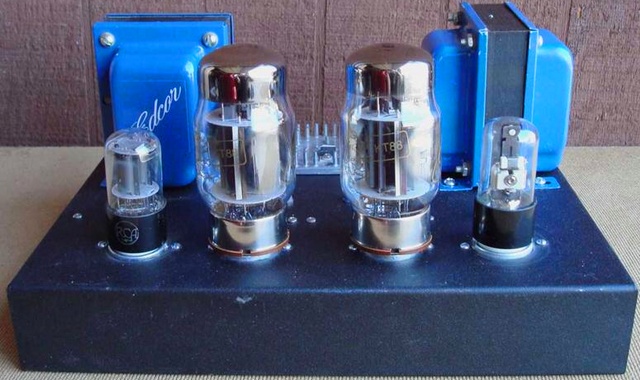
) the sound power amplifier uses the output stage tubes operating in class "A", ultra-linear switching, and is assembled in the form of a monoblock - a tube amplifier. Several different lamps can be used in the circuit, including KT77 / 6L6GC / KT88 with driver on 12SL7... Regardless of what types of lamps are used for output, the sound is velvety and exquisite.
In the driver ( pre-amplifier sound) the lamp operates in dynamic load mode - SRPP. An alternative driver can be made using 5751
... Other options are not excluded, such as 12AU7, 12AT7 and 12AX7... The output power of this circuit can be as high as 50 watts.
The circuit is quite simple, as for the lamp UMZCH, but if you are not familiar with lamp equipment or do not have experience in installing high voltages, then this is not an entirely suitable project for debut... To completely exclude the mutual influence of individual channels (left and right), constructively everything is made as monoblocks - each with its own power supply unit. On the one hand, this option is more complicated and expensive, but it also has its own advantages.
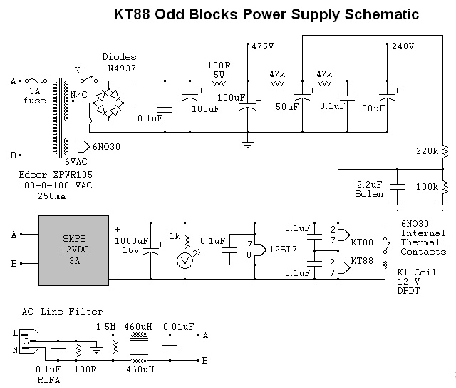
The lower figure shows the simplest. A conventional transformer, rectifier, filter can be used in the power supply. Filament winding 6 volts and 4 amperes. Using only 6.3-volt lamps, the voltage is correspondingly reduced to the above-mentioned level on the incandescence.
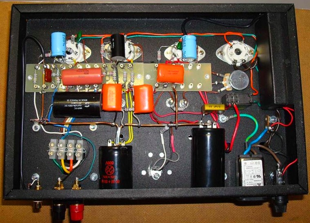
The more sensitive circuit circuits are placed as far away from the power transformers... The filter capacitors were glued to the chassis. Using the ground in the form of thick, large, bare copper wire has been proven to minimize hum, noise, and the ability to optimize ground loops. With the correct connection of all elements of the circuit, the current is 1.25 divided by the value of the resistors. Thus, 10 ohms will result in 0.125 amperes of current (180 mA is required when using KT88 lamps).
Amplifier setup and testing
Just be warned that there are lethal voltages in this circuit, use extreme caution when making any measurements. First turn on the power and check the voltages. There should be 12 volts DC between the 12SL7 filament and about 475 volts across the filter capacitor bank. Insert the lamps. Follow possible problems(inside the lamps there are plates glowing red, sparks, smoke, noise and other interesting things that indicate bad news). Check the voltage again. They must be in the correct ranges. If they are very different, then something is connected incorrectly.
If everything is OK, turn off the power and screw the speakers to the output. Turn on the power again. There should be little or no sounds (noise or noise). If you can hear a slight hum at 10-20 cm from the speaker, then, probably, there are problems with the installation (screen, weight ...).
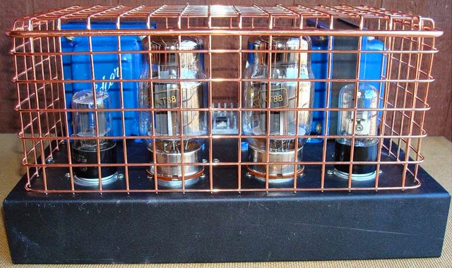
Apply a signal to the amplifier input and see what happens. The sound should be warm and soft with no noticeable distortion. Now is the time to balance the current on the output tubes with a 25 Ohm trimmer. Let the amplifier run for at least 20 minutes and check the settings again. They've probably changed a bit - adjust. After final assembly, it is best to cover hot and hazardous lamps with a safety net (especially if you have pets or children). Enjoy your listening!