The invention relates to electrical engineering and is intended, in particular, to convert one AC system to another. The technical result consists in reducing the impact of the secondary winding on the primary. Resonant transformer contains a magnetic circuit (1), a primary winding (2), a secondary winding (3) and a capacitor (4). The magnetic circuit (1) has elongated rods and yokes. The secondary winding (3) is symmetrically removed from the magnetic circuit (1) and, together with the primary (2), is located around one rod. The primary circuit of the transformer is brought into the resonance mode of currents by parallel connection capacitor (4) and primary winding (2). 4 ill.
Drawings to the RF patent 2418333
The invention relates to the field of electrical engineering and is intended, in particular, for converting one AC system into another in the absence of the effect of the secondary winding on the primary.
The applicant knows the closest prototype of the claimed invention as the closest to him in terms of the set of essential features. This prototype is power transformer containing a magnetic circuit made of electrical steel, primary and secondary windings located on the rods, and the primary winding is connected to an alternating voltage source, and the secondary winding to the load (Katsman M.M. Electric machines. - M .: Higher school, 1983 G., p. 13).
The disadvantage of this transformer is the effect of the secondary winding on the magnetic circuit of the transformer through its magnetic field and as a consequence, the impact on the physical processes occurring in the primary winding circuit, which affects the operating mode of the power supply, depending on the load in the secondary circuit of the transformer.
The problem to be solved by the invention is to eliminate the effect of the secondary winding on the magnetic circuit of the transformer by means of its magnetic field.
This task is achieved by the fact that the resonant transformer contains a magnetic circuit 1, a primary winding 2, a secondary winding 3 and a capacitor 4, the magnetic circuit 1 has elongated rods and yokes, and the secondary winding 3 is symmetrically removed from the magnetic circuit 1 and, together with the primary 2, is located around one rod, moreover, the primary circuit of the transformer is introduced into the resonance mode of currents by parallel connection of the capacitor 4 and the primary winding 2.
The technical result of the invention is the absence of the effect of the secondary circuit of the transformer on its primary circuit through the magnetic field of the secondary winding.
Obtaining the technical result of the invention is possible only due to the symmetrical removal of the secondary winding of the transformer from its magnetic circuit and increasing the magnetizing force of the primary winding, using the increased reactive power in the mode of resonance of currents, obtained by parallel connection of the primary winding of the transformer and the capacitor.
Figure 1 shows the structure of a resonant transformer in section;
Fig. 2 shows the principal electrical circuit connections of the primary and secondary circuits of the resonant transformer;
figure 3 presents a vector diagram explaining the flow of physical processes in the primary circuit of the resonant transformer;
Fig. 4 is a vector diagram for explaining the operation of the resonant transformer.
The resonant transformer shown in Fig. 1 contains a magnetic circuit 1, a primary winding 2 and a secondary winding 3, the magnetic circuit 1 has elongated rods and yokes, and the secondary winding is symmetrically removed from the magnetic circuit and, together with the primary, is located around one rod.
The schematic electrical diagram of the connections of the primary and secondary circuits of the resonant transformer, shown in figure 2, contains a capacitor 4, a resonant transformer 5, a load 6 and operates as follows. The secondary winding of the resonant transformer 5 (Fig. 2) is symmetrically removed from the magnetic circuit at such a distance that when the rated load current flows through it, the EMF of the primary winding is equal to zero. The secondary winding must be removed by at least the value of the magnetic induction in the center of it according to the formula:
D 2 = µ · l 2 · N 2 · f /,
where D is the diameter of the secondary winding frame (m);
µ - magnetic permeability (H / m);
I 2 - current in the secondary circuit (A);
N 2 - the number of turns of the secondary winding;
f is the frequency of the secondary winding current (Hz);
Magnetic line length (m).
Due to the absence of the effect of the remote secondary winding on the magnetic circuit of the resonant transformer, the primary winding of the latter becomes an inductor with a core and is one element of the oscillatory circuit, the second element of which is the capacitor 4. The inductive reactance of the primary winding of the resonant transformer is equal to the reactance of the capacitive nature of the capacitor 4 at a constant frequency supply voltage U 1. Thus, the circuit of the primary winding of the resonant transformer is in the current resonance mode. Due to the effect of increasing the reactive power in the resonance mode, the magnetic field energy of the primary winding increases to the value required to induce the required EMF in the secondary winding to power the load 6. As a result, the resonant transformer operates normally, feeding the load 6, while the physical processes occurring in the primary circuit windings, do not depend on the physical processes occurring in the secondary winding circuit.
As can be seen from the vector diagram (Fig. 3), the current strength of the capacitor I c is many times higher than the current strength of the power supply I and is equal to the current strength of the primary winding of the resonant transformer I 1.
As can be seen from the vector diagram of the resonant transformer (Fig. 4), the primary winding current I 1 does not depend on the load current 1 n and the primary winding has an inductive character, despite the active nature of the load 6, where:
F is the magnetic flux of the resonant transformer (Wb);
I 1 - current strength of the primary winding of the resonant transformer (A);
E 1 - EMF of the primary winding (V);
E 2 - EMF of the secondary winding (B);
U n - voltage across the load (V);
I n - current in the load circuit (A);
I 2X2 - voltage drop across the inductive resistance of the secondary winding (V);
I 2r2 - voltage drop across the active resistance of the secondary winding (V);
I 2z2 - voltage drop across the impedance of the secondary winding (V);
I 1X1 - voltage drop across the impedance of the primary winding (V);
I 1r1 - voltage drop across the active resistance of the primary winding (V);
I 1Z1 - voltage drop across the impedance of the primary winding (V);
CLAIM
A resonant transformer containing a magnetic circuit (1), a primary winding (2), a secondary winding (3) and a capacitor (4), characterized in that the magnetic circuit (1) has elongated rods and yokes, and the secondary winding (3) is symmetrically removed from the magnetic circuit (1) and together with the primary (2) is located around one rod, and the primary circuit of the transformer is introduced into the resonance mode of currents by parallel connection of the capacitor (4) and the primary winding (2).
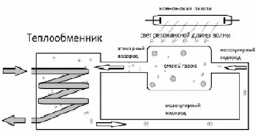
An amazing phenomenon of abnormally high and economical heating of any liquid by an electro-optical method is the thermal electro-optical effect.
The efficiency of direct electro-optical heating of a certain volume of liquid to a given temperature using krypton fluorescent lamps in comparison with its resistor electric heating element is, according to the results of experiments, from 200 to 300%, i.e. the energy efficiency of such heating of a liquid is two to three times higher than well-known liquid electric heaters (TENs), depending on the type of liquid, the material of the heating tank and the type of high-temperature fluorescent lamps (krypton, xenon, sodium and other lamps).
Such economical electro-optical heating devices are also promising for use in installations for the production of Brown's water H2-fuel gas with its subsequent useful use.
Hydrogen heat generator
The decay of a molecule into atoms is due to the excitation of the gas by light of resonance lengthwaves. The excitation costs are small. The synthesis of hydrogen atoms into a molecule produces significant heat release.Hydrogen dissociates about 1% of the total amount for the filament temperature T = 2400K and almost completely 99% for the temperature T = 7000K.
On the way to pulsed energy
There are already operating experimental heating batteries in Russia,consuming electricity from the network in impulses with a duty cycle of 100.Existing electricity meters with an erroneous algorithm orerroneous program overestimate the real power consumption of such batteries in100 times and thus firmly close their way to the consumer.
The conclusion is terribly simple. Impulse technology requires autonomous closed loop, isolated from the central power supply networks.
A special feature of charging batteries with short high-energy pulses is the so-called “fast charging cycle”. The principle is based on the fact that the speed of movement of ions in the electrolyte is much lower than the speed of propagation electric charges in the explorer. Thus, short high-energy pulses “excite” electrolyte ions, which prevents the emergence of a through current through the battery. In the pauses between pulses, the ions spend their potential for a chemical reaction, as a result of which energy is stored. This allows devices operating on this principle to reduce heat generation in the battery electrolyte and, as a result, speed up the charging of the battery.
Non-magnetic field generated bybifilar non-inductive coil, apparently, wears a gravitationalcharacter.Presumablythe magnetic field "compresses" the field structure of the substance, which leads to a changeorbital speed of rotation of atoms. When acting on a "compressed" atom,the potential unfolds the molecular structure faster. After removal of exposurethe electric and magnetic potential of the substance ion "captures" the energygravitational potential, spending it to create the energy of the ionic potential.
To implement this device, it wasthe well-known phenomenon of voltage resonance is used. And to create a compressorused parallel connection two inductances. One of the inductances- made by a special type of winding, so that adjacent layer conductors intersected at an angle of 90˚. Parallel inductance crosses overconductors of layers at an angle of 45˚, while the current passing through it is weakaffects the conductors of the layers of the first winding.
Close in essenceExperiment. Interferometry of comrade Tesla and
Testing the principles of Tesla interferometry
In this circuit, energy is transferred from the primary coil to the secondary without reverseligature. The signal does not pass without permanent magnets.
For example, a Brazilian transformer has one short-circuited bifilar loop. A collision of streams occurs. Direct current is applied to the input. The current does not know which direction it will flow and changes its direction with a high frequency. Pulse diodes or LEDs can be used to reduce the frequency. A semiconductor is the same impulse device. CE of a Brazilian transformer is about 101%, but an enormous amount of heat is released additionally... In 5 seconds of operation of such a device, all the solders melted.
The device only consumes the idle load of the transformer. The transformer is written with only one AC half cycle. The output is pure sine. The second half-period is obtained due to the EMFself-induction. The second half-cycle in amplitude is induced even more than the primary one.
At the input of the transformer 20 V, at the output of the transformer in resonance we get 60 V. Paper capacitors are not suitable for this circuit. High voltage tantalum film capacitors are excellent. When the transformer is turned on, the short-circuited coil instantly heats up. If idling consumption transformer 60 mA, when the short-circuited loop is turned on in resonance, the consumption is 50 mA. Resonance occurs only when saturated core.
Increase in the economic boiler for thermal energy 20 times!
Safe electricity and Free energyin one bottle!
At a current frequency of 50 kHz, the lamp shines calmly in water, while remaining completely safe! When fingers are immersed in water and the conductors are short-circuited, no electric shock occurs. The 1.5 kV load does not heat the thinnest conductors. Cos f = 1 is practically equal to one.

Valery Belousov
Energy has several types: wired and wireless or cold electricity with superconductivity. Energy does not bite, harmless.On the energy of the earth, ordinary incandescent lamps burn, but they burn after 3 hours. LEDs light up normally and for a long time. Heating elements are heating up.
This energy is not recorded by conventional devices. It can be recorded only by the energy released in the load. Electro-insulating varnish for natural energy is a semiconductor. Therefore, when assembling transformers, the native winding is cut down and replaced with a wire for lighting with plastic insulation.
Example:
- Shapkin's transformer 36/380 V when connecting a 2..3 V battery at the output receives several thousand volts.
- Shapkin's transformer 220 V 50 Hz manufactured according to this technological scheme (probably with a collision of electromagnetic fluxes) is loaded with 2 (two) Heating elements 2.2 kW each, additionally - lighting.
Access for the electromagnetic component of the current is blocked. When one energy overlaps, another energy begins to reveal itself. For feeding Natural energy uses two grounding wires. After starting this circuit (from the author), the grounding inputs change poles within 12 hours. After the installation is determined with the poles and enters the operating mode. One input is a donor with its own pole and potential, and the other is an acceptor, with the other pole and opposite potential (without an electromagnetic component).
We connect the transformer to the diode bridge. We get 30 mV with a minus sign (-). There is energy in the disconnected transformer. Energy flows through the diode bridge in the same direction as conventional electricity. But we have opposite charges. And from how the transformer is coordinated with the system, such will be the efficiency of the device. Either the efficiency is lower by this value, or it will be added, and even with resonance. Then the device will be over single. It is necessary to correctly match the transformer with the entire system so that everything is in "pluses".
Available: ground loop, safety unit with capacitors acting as resistance, dissipative transformer, opposition coil. We cut off electrical energy. A hum is heard - the installation is working. Second ground loop.
Ohm's law no longer works after the capacitor bank. There are already completely different laws. Diode bridge. It also has its own losses, but this is done to better study the energy of the Earth. We charge a block of capacitors (non-polar) 55,000 uF through the diode bridge. The LEDs light up. Next, we charge the block of 55,000 uF polar capacitors. After 5 ... 10 seconds, the LED lights up. In a diode bridge, there are two diodes in one direction, one diode in the opposite direction. We see the one-way movement of Energy. We turn on the voltmeter. 2.73 V - constant and 7 V - change. This energy is seen by all digital and pointer instruments. The energy is wired, but does not carry the energy of light (electromagnetic component). Diodes at 7 V should burn out, and they work as at 3 V. The author connected an oscilloscope - 3 V horizontal line, there is no alternating component.
After cleansing the "White" energy from the Earth's composition, we see the presence of another wire energy that does not have in its technical characteristics light emission factor ( electromagnetic radiation). Unknown AC energy.
For more information, see the website
In 2014, Alexander Andreev slightly changed the resonant transformer circuit described by N.N. Gromov. in 2006, but the energy of the resonant transformer still reduces the cost of electricity by 10 times.
This comes from the resonance generated in the secondary winding of the transformer. With a consumption of only 200 watts from the mains, we can give up to 5 kW to the load.
I took the core from a 1978 French inverter. But you need to look for a core with a minimum content of manganese and nickel, and silicon should be within 3%. Then there will be a lot of freebies. Auto resonance will work. (Auto-resonance was first described in the 1930s by Soviet physicists A.A. Andronov, A.A. The transformer can work on its own. Previously, there were such W-shaped plates on which crystals seemed to be drawn. And now soft plates have appeared, they are not fragile, do not break. Such an old fragile transformer steel is the most optimal for a resonant transformer, modern is not suitable. Silicon dramatically increases electrical resistivity. As a result, power losses from eddy currents in electrical steel are sharply reduced. At the same time, the introduction of silicon reduces the losses due to hysteresis and increases the magnetic permeability in weak and medium fields. (see Electrical steel
http: // electrono.ru/ magnitnye-materialy / elektrotexnicheskaya-stal)
The wiring diagram is shown below.
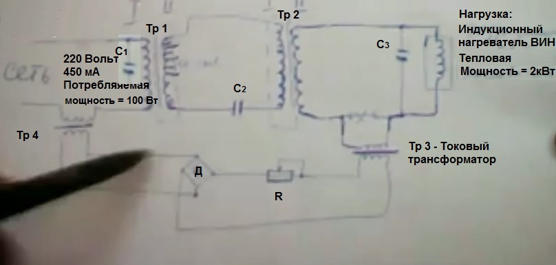
The operation of this transformer is connected to a conventional power grid. While I'm not going to do self-feeding, but it is possible to do it, it is necessary to make the same power transformer, one current transformer and one magnetic reactor around it. All this will be tied up and there will be self-powering .. Another option for self-feeding is to wind a 12-volt removable secondary coil Tr2 on the second transformer, then use a computer UPS, which transfer 220 Volts to the input
The most important thing now is that there is simply a network that is fed to the circuit, and I simply increase the energy due to resonance and power the heating boiler in the house. This is an inductive boiler called VIN. Boiler power 5 kW. This boiler worked for a whole year with my smart transformer. I pay for the network like for 200 watts.
The transformer can be any (on a toroidal or U-shaped core). You just need to insulate the transformer plates well, paint so that the Foucault currents in it are as small as possible, i.e. so that the core does not heat up at all during operation.
Simply resonance gives reactive energy, and by transferring reactive energy to any element of consumption, it becomes active. At the same time, the counter to the transformer does not turn very much.
To search for resonance, I use a Soviet-made ESN-15 device. With it, I can easily achieve resonance in any transformer.
So, for the harsh winter month, I paid 450 rubles.
From the first 1 kW toroidal core transformer, I have 28 amps and 150 volts in the secondary. But feedback is needed through a current transformer. We wind the coils: Make a frame. When the primary is wound around the entire perimeter in two layers (with a wire with a diameter of 2.2 mm, taking into account 0.9 turns per 1 volt, i.e. for 220 Volts in the primary winding, 0.9 turns / V x 220 V = 200 turns ), then I put the magnetic shield (made of copper or brass), when I wound the secondary one (with a wire with a diameter of 3 mm, taking into account 0.9 turns per 1 Volt), then I put the magnetic shield again. On the secondary winding of the first trance, starting from the middle, i.e. with 75 Volts, I made a lot of loop pins (about 60-80 pieces, as many as they can, about 2 Volts per pin). On the entire secondary winding of the first transformer, you need to get 150 - 170 Volts. For 1 kW, I chose a capacitor capacity of 285 μF (the type of starting capacitors used for an electric motor in the figure below), i.e. two capacitors. If I use a 5 kW transformer, then I will use 3 such capacitors (non-polar for AC 100 μF 450 Volts). The manifestation of non-polarity in such a capacitor is insignificant, the smaller the diameter and shorter the jar, the better the non-polarity. It is better to choose shorter capacitors, more v, but less capacitance. At the same time, I found a resonance somewhere in the middle of the terminals of the secondary winding. Ideally, for resonance, measure the inductive resistance and capacitance of the circuit, they should be equal, as in the formula. You will hear the sound of the transformer humming strongly. The resonance sinusoid on the oscilloscope should be perfect. But I determine the resonance by ear, the trance begins to buzz strongly. There are different frequency harmonics of resonance, but at 50 Hz the transformer hums twice as loud as at 150 Hz. From an electrical tool, I used a current clamp that measures frequency. Resonance in the "secondary" causes a sharp drop in the current in the primary winding, which amounted to 120-130 mA. So that there are no complaints from the network company against you, then in parallel with the primary winding of the first transformer, we install a capacitor and bring cos Ф = 1 (by current clamps). I checked the voltage already on the primary winding of the Second transformer. This is at the first transformer. Thus, in this circuit (the secondary winding of the first transformer - the primary winding of the second transformer), I have a current of 28 Amperes. 28A x 200V = 5.6 kW. I remove this energy from the secondary winding of the Second transformer (wire with a cross section of 2.2 mm) and transfer it to the load, i.e. into the electric boiler. For 3 kW, the diameter of the secondary winding of the second transformer is 3 mm
If you want to get the output power on the load, not 1.5 kW, but 2 kW, then the core of the first and second transformers (see dimensional calculation of the core power) should be 5 kW
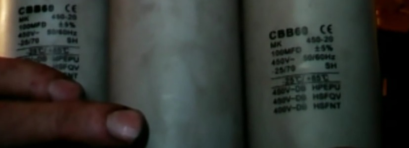
And for the second transformer, the core of which must also be sorted out, paint each plate with balloon paint, remove the burrs, sprinkle with talcum powder so that the plates do not stick to each other), first put the screen, then wind the primary, then put the screen on the "primary" of the second transformer. There must be a magnetic shield between the "secondary" and "primary" all the same. If we got tension in resonant circuit 220 or 300 volts, then the "primary" of the second transformer must be calculated and wound also at the same 220 or 300 volts. If, according to the calculation, 0.9 turns per volt, then the number of turns will be 220 or 300 volts, respectively. Near the electric boiler (in my case, this is a 1.5 kW VIM induction boiler), I put a capacitor, enter this consumption circuit into resonance, then I look at the current or COS Ф so that COS Ф is equal to 1. Thus, the power consumption decreases and I unload the circuit where I have a power of 5.6 kW. I wound the coils as in an ordinary transformer - one above the other. Capacitor 278 uF. I take starter or bias capacitors so that they work well on alternating current. Resonant transformer from Alexander Andreev gives an increase of 1 to 20
The primary winding is calculated as a conventional transformer. When collected, then if the current appears there within 1 - 2 Amperes, then it is better to disassemble the transformer core, see where the Foucault currents are formed and reassemble the core (maybe somewhere something was not painted before or a burr sticks out. Leave the transformer for 1 hour in working order, then feel with your fingers where it has heated up or measured with a pyrometer in which corner it is heated) The primary winding must be wound so that it consumes 150-200 mA at idle.
The feedback circuit from the secondary winding of the second transformer to the primary winding of the primary transformer is necessary for automatic load regulation so that the resonance does not break down. To do this, I placed a current transformer in the load circuit (primary 20 turns, secondary 60 turns and made several taps there, then through a resistor, through a diode bridge and onto a transformer in the line supplying voltage to the first transformer (200 turns / for 60-70 turns)
This scheme is in all ancient textbooks on electrical engineering. It works in plasmatrons, in power amplifiers, it works in a din receiver V. The temperature of both transformers in operation is about 80 C. The variable resistor is a ceramic resistor of 120 Ohm and 150 W, you can put a school nichrome rheostat with a slider there. It also heats up to 60-80 C, since the current passes through it good = about 4 Amperes
Estimate for the manufacture of a Smart transformer for heating a house or summer cottage
Transformers Tr1 and Tr2 = 5,000 rubles each and Tr1 and Tr2 transformer can be bought in the store. It is called a medical transformer. His primary winding is already insulated with a magnetic shield from the secondary. http: // omdk.ru/ skachat_prays
Current transformer Tr3 and trimmer Tr4 = 500 rubles each
Diode bridge D - 50 rubles
Trimmer resistor R 150 W - 150 rubles
Capacitors C - 500 rubles
https: // www.youtube.com/ watch? v = GvaoaKj1xuE
https: // www.youtube.com / watch? v = snqgHaTaXVw
https: / /www.youtube.com/ watch? v = Uu2Rbjr80RI Master class on resonant transformer with Alexander Andreev (part 2)
Tsykin G.S. - Low frequency transformers http: // www.sergey-osetrov.narod2.ru/ Resonant / Transformer_with_low_frequency_M_1955.djvu
Another description of the resonant transformer circuit of Alexander Andreev
On the forum http: // cyberenergy.ru/resonance / generator-aleksandra-t998-40.html, a diagram is shown that allows you to connect a device with a higher power to the load than the power consumed by the device itself.
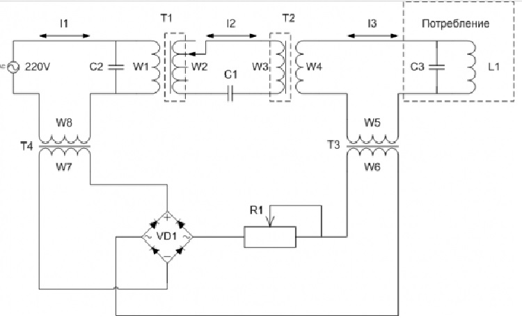
The device operates on transformers at resonance, but without sudden voltage interruptions - without fronts. The W1 winding is the master link for the magnetization reversal of the core. This winding must be wound so that, when turned on, it consumes 150mA at idle (for a 3-kilowatt input transformer T1). Winding W2 is wound so that, starting from its middle, a lot of conclusions are output - about 60-80 conclusions - whoever can do as much as possible, about 2 volts per 1 output. The coil should correspond to 150-160-180V. When adjusting the resonance, the capacitor C1 is switched over the terminals of the winding W2, The resonance of the W2-C1 circuit can be found immediately after being connected to the network. At resonance, the voltage across W2 and C1 reaches 400V. The W3 winding must be wound at the rate of 300V, because it will lower the voltage, almost to 220V, it is also better to do it with unnecessary conclusions in case of a voltage drop.
Transformer T2 is a power, removable transformer. The W2-W3-C1 circuit is well shielded and provides good isolation between power and consumption. The lower part of the circuit is feedback in order to regulate - compare the load with the input so that the resonance does not break down. The capacitor C2 regulates the cosine phi cosφ = 1, so that there are no complaints from the grid company. Parts Used Cores Both W-shaped and toroidal cores are suitable for transformers. In W-shaped windings, it is possible to screen well the windings, but in toroidal ones it is difficult. The core material should be simple - iron. High frequency materials at 50 hertz are inappropriate. To achieve a consumption of 150mA at idle, it is necessary to carefully assemble the core, remove all burrs from the plates, and tint if it is old. Check with a tester whether the plates are short-circuited. In order not to suffer with these plates, you can take a grinding disc and lay them down again - remove all burrs and paint over again with car paint from a spray can, sprinkle with talcum powder so that they do not stick to each other. It is useful to use textolite washers instead of metal ones. If the core is bad, it will heat up due to Foucault currents, the resonance will be weak and the circuit will be ineffective.
Transformer T1. The primary winding W1 of the transformer T1 is wound at the rate of 0.9 turns per 1V for a voltage of 220V, a wire with a diameter of 2.2mm is used. ... The secondary winding of W2 is made of a wire with a diameter of 3 mm, also 0.9 turns per volt. Somewhere from the middle of the winding to its end, conclusions must be drawn every 2 volts. ... Core. It is necessary to carefully assemble the core, remove all burrs from the plates, touch up if it is old. Check with a tester whether the plates are short-circuited. In order not to suffer with these plates, you can take a grinding disc and lay them down again - remove all burrs and paint over again with car paint from a spray can, sprinkle with talcum powder so that they do not stick to each other. For transformer T1, the secondary winding must be screened, and for T2, the primary.
For transformer T1, the secondary winding must be screened, and for T2, the primary.
The W1 winding is the master link for the magnetization reversal of the core. This winding should preferably be wound up so that when turned on, it consumes 150mA at idle (for a 3-kilowatt input transformer T1). To achieve a consumption of 150mA at idle, it is necessary to carefully assemble the core. In the author's first experiment, he had to wind 35 turns and the coefficient of 0.9 turns / volt changed upwards. With the initial number of turns, the idle current was 400mA, and after 35 turns, it was 150mA. Accordingly, treat the rest of the circuit windings carefully and follow them from the point of view of your logic.
Winding W2 is wound so that, starting from its middle, a lot of conclusions are output - about 60-80 conclusions - whoever can do as much as possible, about 2 volts per 1 output. The coil must correspond to 150-160-180V, if desired, you can add it just in case. At resonance, the voltage on W2 will jump above 220V, but this does not mean that W2 should not be wound by 180V, because the resonance will be exactly on these turns, i.e. extra turns are not needed.
Transformer T2
Primary winding W3. The primary winding of W3 is made of a wire with a diameter of 2.2 mm, also 0.9 turns per volt. The W3 winding is wound based on the voltage that is actually present in resonance. At resonance, the actual voltage at W2 exceeds the usual one and goes not only beyond 170V, but also beyond 220V. If, when tuning the resonance in a closed loop, W2-C1 will be 400V, then W3 must be wound at the rate of 300V, because it will lower the voltage, almost to 220V, it is better to do it with unnecessary conclusions in case of a voltage drop. Reminder: W2 should not run at 180V, because the resonance will be precisely on these turns, but the primary W3 of the transformer T2 must be wound for the actual voltage at resonance, i.e. it will have significantly more turns than in the secondary W2.
The secondary winding W4 of transformer T2 can be wound when the circuit of W1, W2 and W3 is configured. Then, having wound 10 turns, you can measure the voltage and find out how many turns are needed to get 220V. For a load of 2kW, a wire with a diameter of 2.2mm can be used.
The core of the T2 transformer must be treated in the same way as the T1 transformer, so that the Foucault currents are minimal. For transformer T1, the secondary winding must be screened, and for T2, the primary.
Demonstration of the T1 / T2 transformer for 14m40s video posted at the beginning of the article.
Transformer T2 has more turns than transformer T1.
If it is necessary to remove 2 kW at the output, then transformer T1 and transformer T2 must be 5 kW each.
Transformer T3
Transformer T3 is a current transformer.
Primary winding W5 has approximately 20 turns
The secondary W6 has about 60 turns and there are several taps so that the circuit with the resistor and diodes does not overload.
Transformer T4
In the primary winding W7 200 turns
Secondary W8 has approximately 60-70 turns.
From each coil of transformers T3 and T4, it is better to make 20 leads for tuning.
Capacitors
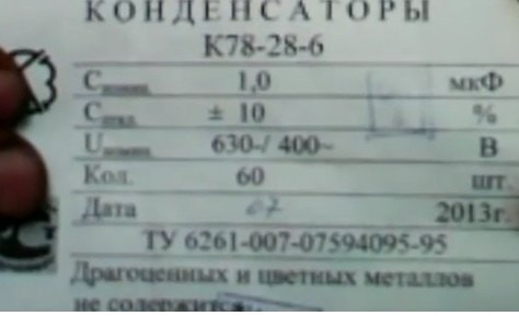
Capacitors should not be a polar electrolyte, but non-polar polymer, or rather a set of them - these can be starter capacitors for alternating current. Capacitors need to be checked that they are not polar - this can be done on an oscilloscope, this is done like this: one wire from the leg of the capacitor is inserted into the oscilloscope, and the other wire from the other leg is taken by the hand and the alternating current pickup is watched on the oscilloscope - what is the amplitude, then the ends of the capacitor change places and again look at the amplitude. The difference in amplitudes is used to estimate the polarity of the capacitor. Symmetry should be obtained with a deviation of no more than 5%. It is necessary to take smaller and shorter capacitors.
Capacitor C1
Capacity C1 - 285μF.
You can take 1μF capacitors and connect them into blocks in a geometric progression (doubling), for example, 1μF, 2μF, 4μF, 8μF, 16μF, 32μF, 64μF, 128μF. Then it will be possible to make a system of them and switches (good push-button switches), which will turn on and off these blocks and due to this it will be possible to obtain any value of the capacitance with an accuracy of 1 μF. For example, 185μF will consist of blocks 128 + 32 + 16 + 8 + 1. Having such a capacitor store, you can save on the number of leads from the W2 winding, because the resonance can still be picked up. Moreover, the resonance will be better if the inductive reactance is equal to the capacitive reactance. They can be calculated by a formula or measured, and if they are not equal, then they must be equal. Capacitor C1 for a 3kW transformer is 285μF. You can use a capacitor of smaller capacity, for example 185 μF, but then the voltage on the secondary W2 will have to be increased and more turns will be wound, and then more turns will be wound on the primary W3 of the T2 transformer.
Capacitor C2
Capacitor C2 depends on how much reactive energy is released back (approximately 40-50 μF). It is needed to make the cosine of the voltage across W1 and C2 and the current I1 equal to one. The cosine is measured with special clamps, which are worn around the wire with current I1 and connected with terminals to W1.
Capacitor C3
Capacitors C2 and C3 remove harmonics.
Resistor R1
Resistor R1 120 Ohm, 150W - ceramic resistor. You can supply a wirewound nichrome variable resistor. Current up to 4A, heats up to 60-80 degrees.
The 1.5 kW induction heating boiler Vin is used as a load.
Build and setup
Assembling transformers
The usual copper lacquered wires (with paint-and-lacquer insulation) are used. In the case of a toroidal transformer T1 First, the primary is wound, then the foil, the secondary, and again the foil. Moreover, the secondary is not wound 360 degrees of the torus, but a gap is left so that in this place the foil of different layers can be brought together (there is no contact - insulation is used). If the turns do not fit into one layer, then you need to skip this free sector and continue to wind the second layer behind it.
Setting up the first transformer, setting the time circuit W2-C1 Initially, the resonance setting on the T1 transformer is performed according to the scheme:
we switch the capacitor along the terminals of the winding W2, while at a current of I12 of 28-30A at resonance there will be a sharp decrease in the current I11 and it will remain within 120-130mA. Those. There is no need to connect the load, a clean LC circuit should remain. When there is resonance, the transformer will begin to hum badly. By adding capacitors of 1 μF to C1, the voltage on the W3 coil will increase, but if after that it starts to drop with the addition of capacitors to C1, then this means that we have crossed the resonance - we need to remove the capacitors again.
Then we connect the transformer T2 - this is a power, removable transformer. Perhaps you have not yet wound the secondary winding W4 of the transformer T2. The resonance can be found immediately after plugging into the network. As long as there is no load, the resonance normally lasts for a long time. After warming up the transformer (after 20-30 minutes), you can make the adjustment again by running capacitor C1 along the terminals of the coil W2. At resonance, the voltage across W2 and C1 reaches 400V. The continuation of tuning the resonance is continued below in the description of the capacitor C1.
Having the capacitor store described above (1 + 2 + 4 + ...), you can save on the number of terminals from the W2 winding, because the resonance can still be picked up. Moreover, the resonance will be better if the inductive reactance is equal to the capacitive reactance. They can be calculated by a formula or measured, and if they are not equal, then they must be equal. If the resonance is not good, then at the output of W2 there will be a sinusoid worse than at the input of W1, and it (at W2) should be ideal. This can be done by ear. The better the transformer hums, the better the resonance. At resonance, the transformer should hum the loudest and the hum should be at a frequency of 50Hz, i.e. the lowest frequency. If the resonance is at a frequency of 150 Hz, and not 50 Hz, then the current I1 - consumption from the network (to the coil W1) will be higher. At the most correct resonance, the current I1 is minimal. After the resonance is found at the terminals of the coil W2, you can adjust the capacitance C1.
Load mode
Coil W2 is disconnected from the magnetic connection with W1 due to the fact that it is in the shield. Also, the W3 coil is disconnected from W4, due to this, the W2-W3-C1 circuit begins to work well - it is unloaded and thus also. Then this circuit keeps resonance well - it does not break. The resonance of the transformer T1 is checked after switching on as follows: if the winding W1 heats up more than the core, then everything is normal - there is resonance, and if the core heats up more than the winding, then the transformer was assembled incorrectly. A place in the core that begins to heat up more is easy to find if there is a pyrometer - it could be a bolt zone or something else and an assembly error.
In the W2-W3-C1 circuit, a current of 28A rotates. On the winding W4, the measurements show a voltage of 220V.
At resonance, the 3kW core of the T1 transformer heats up to 80-90 degrees. Transformer T2 also heats up within 80 degrees. If the power of the W2-W3-C1 circuit is 5kW, then only 1.5-2kW of power can be removed at the L1 output, because the circuit begins to break down due to heating of the core. Those. if it is necessary to remove 2 kW at the output, then transformer T1 and transformer T2 must be 5 kW each.
Voltage
W1 - 210-230V - what comes from the mains.
W2 - in resonance of a short circuit 400V.
W3 - at resonance 230V.
W4 is too high - 240-250V, so that the heater warms up better.
Setting up capacitor C3
At the output, a 1.5 kW induction heater - L1 is used as consumption. By adding the capacitance C3, we introduce into resonance at the minimum current W4-L1 or the cosine phi should be 1 (if adjusted by cosine, then the current clamps are connected to the terminals L1, and they themselves are put on the conductor W4-L1) - then the power consumption decreases and the circuit W2- W3-C1 is unloading.
Configuring Capacitor C2
The capacitor C2 regulates the cosine phi cosφ = 1, so that there are no complaints from the grid company. Capacitor C2 depends on how much reactive energy is released back (approximately 40-50 μF). It is needed to make the cosine of the voltage across W1 and C2 and the current I1 equal to one. The cosine is measured with special clamps, which are worn around the wire with current I1 and connected with terminals to W1.< http://www.sergey-osetrov.narod.ru/2-2-3.gif
Bottom of the diagram
The lower part of the circuit (T3 ⇐ = ⇒ T4) is a feedback in order to regulate - compare the load with the input so that the resonance does not break down.
Auto-adjustment goes approximately as follows: during heating, if the current in W5 decreases, then in W6 it decreases, in W7 it decreases and in W8 the voltage decreases, moreover, it is possible that the connection of the transformer T4 is confused in the circuit and it must be connected with the opposite polarity so that the voltage produces the opposite the effect. From each coil of transformers T3 and T4, it is better to make 20 leads for tuning.
Device characteristics
The consumption of the device without a load is 200mA, and with a load of 350mA. Load 1.5kW. It is necessary to adjust the resonance several times a day. The cores of the transformers T1 and T2 and the resistor R1 heat up to 70-90 degrees
Smart simplified Andreev transformer on the W-shaped core or how to make an electricity generator from a choke
This is the principle of a choke and a transformer rolled into one, but it is so simple that no one has yet guessed to use it. If we take the W-shaped core of a 3-phase transformer, then the functional diagram of the generator for obtaining additional energy will be as in the figure below
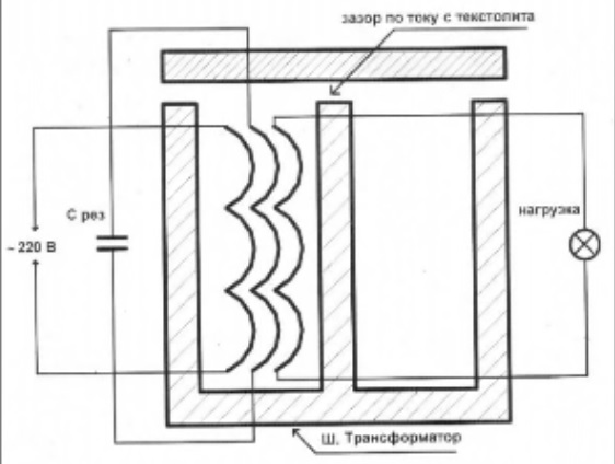
This generator of electricity combines the principle of a choke and a transformer in one person, but it is so simple that no one has yet guessed to apply it. To get a larger reactive current in the resonant circuit, you must turn the transformer into a choke, that is, break the transformer core completely.
All you need to do is wind not the input winding first, as is usually done, but the output winding, i.e. the one where the energy is taken.
We wind the second resonant. In this case, the diameter of the wire should be 3 times thicker than the power one
In the third layer we wind the input winding, that is, the mains winding.
This is a condition for the resonance between the windings to walk.
And so that there is no current in the primary winding, we turn the transformer into a choke. Those. We collect W-images on one side, and we collect lamellas (plates) on the other side. And there we expose a gap. The gap should be according to the power of the transformer. If 1 kW, then he has 5 A in the primary winding. We make the gap so that there is 5A idle in the primary winding without load. This needs to be achieved with a gap. Then, when we do the resonance, the current drops to "0" and then you will gradually connect the load, connect and watch the difference between the power input and power output, and then you will get a freebie. I achieved a 1: 6 ratio with a 1-phase 30kW transformer (in terms of power 5A - at the input and 30A - at the output)
Only it is necessary to gradually gain power so as not to jump over the barrier of the halavschina. Those. as in the first case (with two transformers), the resonance exists up to a certain load power (less is possible, but no more is possible) This barrier must be selected manually. You can connect any load (active, inductive, pump, vacuum cleaner, TV, computer ...) The load must be coordinated so that there is no overkill of this power. When the power is overkill, then the resonance goes away, then the resonance stops working in the energy pumping mode.
By design
I took an E-core from a 1978 French inverter. But you need to look for a core with a minimum content of manganese and nickel, and silicon should be within 3%. Then there will be a lot of freebies. Autoresonance will work. The transformer can work on its own. Previously, there were such W-shaped plates on which crystals seemed to be drawn. And now soft plates have appeared, they are not fragile, unlike old iron, but soft and do not break. This old iron is the most optimal for a transformer.
If you do it on a torus, then you need to saw the torus in two places, so that you can make a tie later. You need to grind the sawn gap very well.
On a W-shaped 30 kW transformer, I got a gap of 6 mm, if 1 kW, then the gap will be somewhere 0.8-1.2 mm. Cardboard will not work as a spacer. Magnetostriction gouges it. Better to take fiberglass
The first winding is wound, which goes to the load, it and all the others are wound on the central rod of the W-shaped transformer. All windings wind in one direction
The selection of capacitors for the resonant winding is best done with a capacitor store. There is nothing complicated there. It is necessary to ensure that the iron begins to growl well, that is, ferro-resonance appears. Not an induction effect between the capacitor and the coil, but for the iron between them to work well. Iron must work and pump energy, resonance itself does not pump, and iron is a strategic device in this device.
My resonant winding had 400 volts. But the more, the better. Regarding resonance, you need to observe the reactance between the inductance and the capacitance so that they are equal. This is the point where and when resonance occurs. You can also add resistance in series.
50 Hz comes from the mains, which excite resonance. There is an increase in reactive power, then with the help of a gap on the plate in a removable coil, we convert reactive power into active power.
In this case, I was just going to simplify the circuit and switch from 2x transformer or 3x transformer, circuits with feedback and throttle. Here I have simplified to such an option, which also works. The 30 kW-th power works, but I can take off the load only 20 kW, because everything else is for pumping. If I take more energy from the network, then he will give more, but the freebie will decrease.
Another unpleasant phenomenon associated with chokes should be mentioned - all chokes, when operating at a frequency of 50 Hz, create a humming sound of one intensity or another. According to the level of noise produced, chokes are divided into four classes: with normal, reduced, very low and especially low noise levels (in accordance with GOST 19680, they are marked with the letters H, P, C and A).
Core noise is generated by magnetostriction (reshaping) of the core plates as a magnetic field passes through them. This noise is also known as idle noise because it is independent of the load applied to the inductor or transformer. Load noise occurs only with the transformers to which the load is connected and is added to the idle noise (core noise). This noise is caused by electromagnetic forces associated with the scattering of the magnetic field. The sources of this noise are the casing walls, magnetic shields, and vibration of the windings. Core and winding noise is mainly in the 100-600 Hz frequency range.
Magnetostriction has a frequency twice the frequency of the applied load: at a frequency of 50 Hz, the core plates vibrate at a frequency of 100 times per second. Moreover, the higher the magnetic flux density, the higher the frequency of the odd harmonics. When the resonant frequency of the core or housing matches the drive frequency, the noise level increases even more.
It is known that if a large current flows through the coil, the core material is saturated. Choke core saturation can lead to increased core material losses. When the core is saturated, its magnetic permeability decreases, which leads to a decrease in the inductance of the coil.
In our case, the core of the inductor is made with an air dielectric gap in the path of the magnetic flux. The air-gap core allows:
Eliminate core saturation, reduce power losses in the core, increase coil current, etc.
Choke selection and core characteristics. Core magnetic materials are composed of very small magnetic domains (on the order of a few molecules). When there is no external magnetic field, these domains are randomly oriented. When an external field appears, the domains tend to align along its lines of force. In this case, a part of the field energy is absorbed. The stronger the external field, the more domains are completely aligned along it. When all domains are oriented along the lines of force of the field, a further increase in magnetic induction will not affect the characteristics of the material, i.e., saturation will be achieved. As the strength of the external magnetic field begins to decrease, the domains tend to return to their original (chaotic) position. However, some domains retain their order, and part of the absorbed energy, instead of returning to the external field, is converted into heat. This property is called hysteresis. Hysteresis loss is the magnetic equivalent of dielectric loss. Both types of losses occur due to the interaction of the electrons of the material with the external field. http: // issh.ru/ content / impulsnye-istochniki-pitanija / vybor-drosselja / kharakteristiki-serdechnika / 217 /
The analytical calculation of the air gap in the throttle is not very accurate, because Manufacturers' data on steel magnetic cores is inaccurate (typically +/- 10%). The Micro-cap circuit simulation program allows you to fairly accurately calculate all the parameters of the inductors and the magnetic parameters of the core http://www.kit-e.ru/ articles / powerel / 2009_05_82.php
Influence of the air gap on the quality factor Q of the steel core choke. If the frequency of the voltage applied to the choke does not change and with the introduction of an air gap into the core, the voltage amplitude increases so that the magnetic induction is kept constant, then the core losses will remain the same. The introduction of an air gap into the core causes an increase in the magnetic resistance of the core in inverse proportion to m∆ (see formula 14-8) Therefore, to obtain the same magnetic induction of magnetization, the current must increase accordingly. The quality factor Q of the choke can be determined by the equation
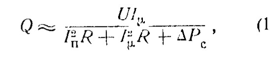
To obtain the highest quality factor, an air gap is usually introduced into the choke core, thereby increasing the current Im so that equality 14-12 is satisfied. Since the introduction of an air gap reduces the inductance of the choke, a high Q value is usually achieved by reducing the inductance.
http: // edu.sernam.ru/ book_dpt.php? id = 3
| Created by 12 Aug 2017 | |||||||||